1.1 ADCHS Interrupt
This example application shows how to sample an analog input using the ADCHS peripheral and displays the converted samples on a serial terminal.
Description
In this application, an analog input is converted by a hardware trigger generated by the TMR peripheral. Result is read in the conversion complete interrupt handler. Converted digital value is displayed on the serial terminal.
Downloading and Building the Application
To clone or download this application from Github, go to the main page of this repository and then click Clone button to clone this repository or download as zip file. This content can also be downloaded using content manager by following these instructions.
Path of the application within the repository is apps/adchs/adchs_interrupt/firmware.
To build the application, refer to the following table and open the project using its IDE.
| Project Name | Description |
|---|---|
| pic32mz_dag_sk.X | MPLABX project for PIC32MZ Embedded Graphics with Stacked DRAM (DA) Starter Kit |
| pic32mz_das_sk.X | MPLABX project for PIC32MZ Embedded Graphics with Stacked DRAM (DA) Starter Kit (Crypto) |
Setting Up the Hardware
The following table shows the target hardware for the application projects.
| Project Name | Description |
|---|---|
| pic32mz_dag_sk.X | PIC32MZ Embedded Graphics with Stacked DRAM (DA) Starter Kit |
| pic32mz_das_sk.X | PIC32MZ Embedded Graphics with Stacked DRAM (DA) Starter Kit (Crypto) |
Setting Up PIC32MZ Embedded Graphics with Stacked DRAM (DA) Starter Kit
- Connect the AN3 pin RB15 (Pin 36 of the J15) to the VCC (Pin 1 of the J15)
- Connect the COM port J5(UART-USB) to the computer using a micro USB cable
- Connect the Debug USB port on the board to the computer using a micro USB cable
Setting Up PIC32MZ Embedded Graphics with Stacked DRAM (DA) Starter Kit (Crypto)
- Connect the AN3 pin RB15 (Pin 36 of the J15) to the VCC (Pin 1 of the J15)
- Connect the COM port J5(UART-USB) to the computer using a micro USB cable
- Connect the Debug USB port on the board to the computer using a micro USB cable
Running the Application
- Open the Terminal application (Ex.: Tera term) on the computer
- Connect to the “USB to UART” COM port and configure the serial settings as
follows:
- Baud : 115200
- Data : 8 Bits
- Parity : None
- Stop : 1 Bit
- Flow Control : None
- Build and Program the application project using its IDE
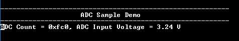
- Console displays the ADC count and the ADC input voltage