1.4 CMP Configurable Reference
This example application shows how to use the CMP Peripheral library to compare voltage level on the negative input with the internal configurable reference voltage.
Description
The peripheral named comparator voltage reference (CVR) can be used by the CMP peripheral. It generates a voltage that can be connected internally to the +ve input of the any of the comparators in the device. This allows to set flexible compare voltages.
Downloading and Building the Application
To clone or download this application from Github, go to the main page of this repository and then click Clone button to clone this repository or download as zip file. This content can also be downloaded using content manager by following these instructions.
Path of the application within the repository is apps/cmp/cmp_configurable_reference/firmware.
To build the application, refer to the following table and open the project using its IDE.
| Project Name | Description |
|---|---|
| pic32mz_dag_sk.X | MPLABX project for PIC32MZ Embedded Graphics with Stacked DRAM (DA) Starter Kit |
| pic32mz_das_sk.X | MPLABX project for PIC32MZ Embedded Graphics with Stacked DRAM (DA) Starter Kit (Crypto) |
Setting Up the Hardware
The following table shows the target hardware for the application projects.
| Project Name | Description |
|---|---|
| pic32mz_dag_sk.X | PIC32MZ Embedded Graphics with Stacked DRAM (DA) Starter Kit |
| pic32mz_das_sk.X | PIC32MZ Embedded Graphics with Stacked DRAM (DA) Starter Kit (Crypto) |
Setting Up PIC32MZ Embedded Graphics with Stacked DRAM (DA) Starter Kit
- Connect the Debug USB port on the board to the computer using a micro USB cable
- Connect the USB to UART port on the board to the computer using a micro USB cable
- Pin 27 (C2INB) on J15 is the negative input. Connect it to a voltage below the reference voltage (~2V from CVR peripheral) to trigger interrupt
Setting Up PIC32MZ Embedded Graphics with Stacked DRAM (DA) Starter Kit (Crypto)
- Connect the Debug USB port on the board to the computer using a micro USB cable
- Connect the USB to UART port on the board to the computer using a micro USB cable
- Pin 27 (C2INB) on J15 is the negative input. Connect it to a voltage below the reference voltage (~2V from CVR peripheral) to trigger interrupt
Running the Application
- Open the Terminal application (Ex.: Tera term) on the computer
- Connect to the “USB to UART” COM port and configure the serial settings as
follows:
- Baud : 115200
- Data : 8 Bits
- Parity : None
- Stop : 1 Bit
- Flow Control : None
- Build and Program the application project using its IDE
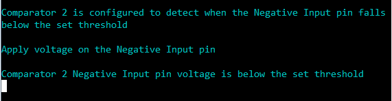
- Following message is output on console: