
1 Hardware Description
Microchip provides several PRIME FW stack libraries for the Base Node. All of them are fully functional and the only difference resides in the number of supported nodes. Depending on the Hardware, the maximum number of Service Nodes to be supported by the PRIME Base Node are different. In addition, the only HW interface between the Host and the PRIME Base Node Modem is a Serial Port or a USB.
- SAMA5D27-SOM1-EK1
- https://www.microchip.com/developmenttools/ProductDetails/atsama5d27-som1-ek1
Figure 1-1. SAMA5D27-SOM1-EK1 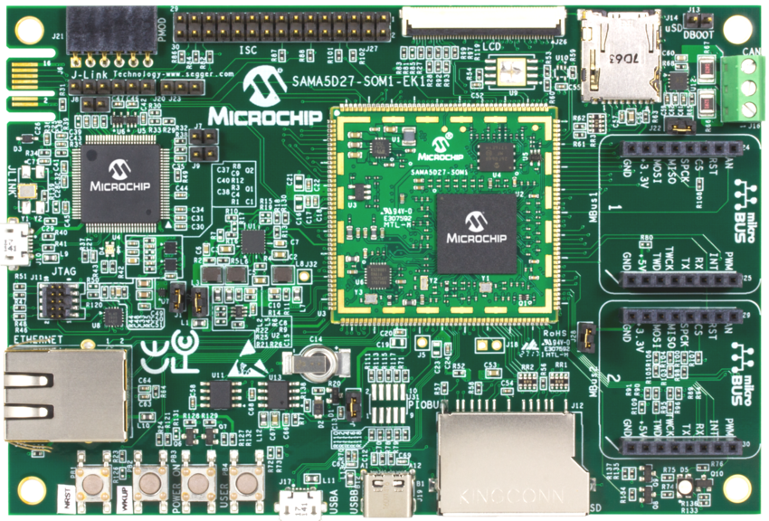
- https://www.microchip.com/developmenttools/ProductDetails/atsama5d27-som1-ek1
- PL360G55CF-EK
- https://www.microchip.com/developmenttools/ProductDetails/pl360g55cf-ek1
Figure 1-2. PL360G55-CF EK 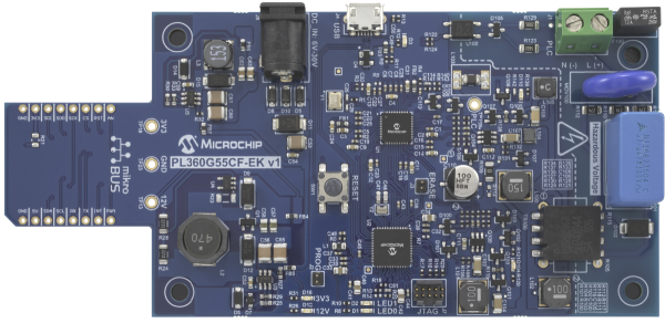
- https://www.microchip.com/developmenttools/ProductDetails/pl360g55cf-ek1
Both boards are available as evaluation kits from Microchipdirect.com and distributors, containing software, hardware schematics, Bill of Materials and PCB designs.
The SAMA5D27-SOM1-EK1 includes two mikroBUS™ connectors where PL360G55CF-EK could be connected. MikroBUS 1 is used by default. Figure 1-3 and Figure 1-4 show the mikroBUS schematic on both evaluation kits.


The SAMA5D27-SOM1-EK1 is powered by USB and PL360G55CF-EK is powered by a 5V pin in the mikroBUS™. The project is using mikroBUS 1 of SAMA5D27-SOM1-EK1; therefore, verify in the SAMA5D27-SOM1-EK1 board that the resistor R80 is soldered to enable the 5 Volts pin to supply power (in case of using mikroBUS 2, the resistor to check is R109).
An SD card is also required to run the Linux™ image of the project. The SD card is connected to the SD connector of the SAM5D27-SOM1-EK1 (J12).
It is also possible to run the application with a native Linux™ machine or in a Windows environment (like CYGWIN or Windows 10 WSL) by connecting a USB cable directly to the microUSB port of the PL360G55 board. (It appears like a Serial Port on the Host side).