
Getting Started
Requisites
- Two PL485-EK boards
- PC host(s) with serial terminal emulator (e.g. PuTTY)
Power-Up
The board has to be powered by means of the included USB cable or from an external DC power supply ranging from 6V to 48V. Refer to the PL485-EK User Guide for more details about the power supply requirements. When the board is powered, the 3V3 and 5V LEDs turn on.
The PHY PLC&Go example runs a chat application between two or more endpoints using Microchip PLC modem boards. Any endpoint can transmit a message, which is received by the other endpoints in the network. LED0 (green) blinks to indicate that the application is running. LED1 (red) flashes when a PLC message is received, and LED D15 (yellow) flashes at each transmission.
If the PHY PLC&Go example is not programmed in the board, the latest version of the code can be found in the \thirdparty\g3\phy\atpl360\apps\phy_plc_and_go\samg55j19_pl485_ek_cenb folder of the Microchip G3-PLC stack.
Running PHY PLC&Go
- Connect each PL485-EK board to the PC host using the included micro USB cable and the USB device connector (J5). A virtual COM port will be enumerated for each board. If required, install the Atmel USB CDC Virtual COM driver.
- Run two terminal emulators, selecting
the serial COM port assigned to each board at 921600bps.
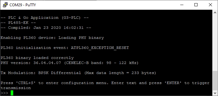
- Send a message from one board by writing any text in the terminal emulator and pressing ‘ENTER’. The message is received and shown in the terminal emulator of the other board.
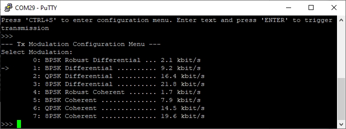
- Modify the transmission configuration
by pressing ‘CTRL+S’ in the terminal emulator to test the different
modulations.
For more information about the PHY PLC&Go example, refer to the AN3400 - PLC and Go application note.