
4.2 Jumper Options
The CEC173x evaluation board has a variety of configuration jumpers.
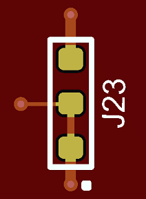
The jumpers and headers have a J reference designator. Several of the jumpers have been replaced by a special trace-link PCB structure, in which the default value for the jumper is hardwired into the design. A representative picture of this PCB structure for jumper J23 is shown in the figure below, labeled “Trace-Link Jumper”. To change the value of these jumpers, the user must cut the default trace and install a resistor across the alternate connection pads. For instance, to change the configuration of J23, cut the trace between pins 1 and 2, and install a zero Ohm 0603 surface-mount resistor between pads 2 and 3. In some cases, jumpers have been replaced with a single 0 Ohm resistor. For these jumpers, the options are either installed (IN) or not installed (OUT). The resistors used in these locations are listed in Table 4-1. In other cases, a standard jumper cap must be placed across jumper pins in the default position for default operation of the device.
- Standard – A standard jumper uses a header and a jumper cap to modify the design.
- 0 Ohm Short – Instead of a selection jumper, one or more zero Ohm jumpers were used to replace the original jumper. The Configuration Options column indicates which resistors were used to replace the jumper.
- Trace-Link – A PCB structure that shorts through a direct metal link to the default position
- Header – Not a jumper, but a header to interface with the outside world.
- Removed – A jumper that existed on the original EV19K07A board but was removed from the EV42J24A board.
| Jumper | Function | Board Rev 2/3 Jumper Type | Configuration Options |
|---|---|---|---|
| J1 | Board Power Selection | Standard | 1-2: Power by external 5V Adapter
(P1) 2-3 (Default): Power by micro-USB Port (P2, P3) |
| J2 | VTR power to CEC173x | 0 Ohm Short - R163 | IN (Default): Connect VTR power OUT: Disconnect VTR power |
| J3 | +3.3V power to MEC1723 | 0 Ohm Short - R166 | IN (Default): Connect +3.3V power OUT: Disconnect +3.3V power |
| J4 | VTR_PLL power to CEC173x | 0 Ohm Short - R164 | IN (Default): Connect VTR_PLL power OUT: Disconnect VTR_PLL power |
| J5 | +1.8V power to MEC1723 | 0 Ohm Short - R167 | IN (Default): Connect +1.8V power OUT: Disconnect +1.8V power |
| J6 | CEC173x I2C SCL selection to MCP2221A | Standard | 1-2: I2C10 3-4 (Default): I2C06 5-6: I2C00 |
| J7 | VTR_ANALOG power to CEC173x | 0 Ohm Short - R165 | IN (Default): Connect VTR_ANALOG
power OUT: Disconnect VTR_ANALOG power |
| J8 | +3.3V power to CEC173x | 0 Ohm Short - R168 | IN (Default): Connect +3.3V power OUT: Disconnect +3.3V power |
| J9 | +1.8V power to CEC173x | 0 Ohm Short - R169 | IN (Default): Connect +1.8V power OUT: Disconnect +1.8V power |
| J10 | VTR1 power selection for CEC173x | Standard | 1-2 (Default): Connect +3.3V power 3-4: Connect +1.8V power |
| J11 | CEC173x I2C SDA selection to MCP2221A | Standard | 1-2: I2C10 3-4 (Default): I2C06 5-6: I2C00 |
| J12 | VTR2power selection for CEC173x | Standard | 1-2 (Default): Connect +3.3V power 3-4: Connect +1.8V power |
| J13 | VTR_REG power to MEC1723 | 0 Ohm Short - R170 | IN (Default): Connect VTR_REG power OUT: Disconnect VTR_REG power |
| J14 | VTR2 power selection for MEC1723 | Rev 2: Trace-Link | Rev 2: 1-2 (Default): Connect +3.3V power 3-4: Connect +1.8V power |
| Rev 3: Standard | Rev 3: 1-2 (Default): Connect +3.3V power 2-3: Connect +1.8V power | ||
| J15 | VTR_PLL power to MEC1723 | 0 Ohm Short - R173 | IN (Default): Connect VTR_PLL power OUT: Disconnect VTR_PLL power |
| J16 | VTR_ANALOG power to MEC1723 | 0 Ohm Short - R175 | IN (Default): Connect VTR_ANALOG
power OUT: Disconnect VTR_ANALOG power |
| J17 | VTR1 power to MEC1723 | 0 Ohm Short - R176 | IN (Default): Connect VTR1 power OUT: Disconnect VTR1 power |
| J18 | VBAT power to MEC1723 | 0 Ohm Short - R177 | IN (Default): Connect VBAT power OUT: Disconnect VBAT power |
| J19 | VTR3 power to MEC1723 | 0 Ohm Short - R178 | IN (Default): Connect VTR3 power OUT: Disconnect VTR3 power |
| J20 | CEC173x GPIO012/nEXTRST Pull selection | Trace-Link | 1-2 (Default): Pull-high to VTR_REG 2-3: Pull-down |
| J21 | CEC173x GPIO106/AP0_nRESET Pull selection | Trace-Link | 1-2 (Default): Pull-high to VTR_REG 2-3: Pull-down |
| J22 | CEC173x GPIOs Header | Header | For debug purposes |
| J23 | CEC173x GPIO1316/AP1_nRESET Pull selection | Trace-Link | 1-2 (Default): Pull-high to VTR_REG 2-3: Pull-down |
| J24 | CEC173x nRESET_IN pin | Standard | 1-2 (Default): Normal operation 2-3: Hold CEC1736 in reset |
| J25 | CEC173x JTAG _STRAP pin | Trace-Link | 1-2: Put in boundary scan mode 2-3 (Default): Normal operation |
| J26 | CEC173x GPIO055 Strap Option | Trace-Link | 1-2 (Default) |
| J27 | CEC173x I2C_ADDR0 Strap | Trace-Link | 1-2: Pull-high to VTR_REG 2-3 (Default): Pull-down |
| J28 | CEC173x CR_FLASH Strap | Trace-Link | 1-2 (Default): Normal operation 2-3: Boot from crisis recovery Flash component |
| J29 | CEC173x GPIO124 Strap Option | Trace-Link | 1-2 (Default) |
| J30 | CEC173x BSTRAP Strap | Standard | 1-2 (Default): Normal operation 2-3: Boot from I2C or UART Crisis Port |
| J31 | CEC173x I2C_ADDR1 Strap | Trace-Link | 1-2: Pull-high to VTR_REG 2-3 (Default): Pull-down |
| J32 | CEC173x RESET_IN# Delay Circuit Power Source | Trace-Link | 1-2 (Default): Connect +3.3V power 2-3: Connect VTR_REG power |
| J33 | CEC173x PICKIT4 1x8 Header | Header | For debug purposes |
| J34 | CEC173x 32KHz Single-End Source | 0 Ohm Short - R151 | IN (Default): Connect oscillator OUT: Disconnect oscillator |
| J35 | CEC173x RESET_IN# delay circuit | 0 Ohm Short - R152 | R152 IN (Default): Connect delay
circuit OUT: Disconnect delay circuit |
| J36 | CEC173x GPIO157/LED1 & GPIO156/LED0 pins connection | 0 Ohm Short | R154 1-2 (Default): Connect GPIO157 to
LED5 R155 3-4 (Default): Connect GPIO156 to LED6 |
| J37 | CEC173x RESET_IN# pin ground | 0 Ohm Short - R153 | IN: Hold CEC1736 in Reset OUT (Default): Normal operation |
| J38 | CEC173x UART0 debug header | Standard | For debug purposes |
| J39 | MEC1723 Test Clocks Out header | Standard | For debug purposes |
| J40 | MEC1723 32KHz Single-End Input selection (Optional) | 0 Ohm Short | Use R180, R181 and R67 to select the clock source |
| J41 | MEC1723 I2C02 channel header | Standard | For debug purposes |
| J42 | MEC1723 I2C07 channel header | Standard | For debug purposes |
| J43 | MEC1723 RESET_IN# delay circuit | Standard | IN: Connect delay circuit OUT (Default): Disconnect delay circuit |
| J44 | MEC1723 RESET_IN# pin ground | Rev 2: 0 Ohm Short - R156 | Closed: MEC1723 in reset IN: Hold MEC1723 in reset OUT (Default): Normal operation |
| Rev 3: Standard | Rev 3: Closed: MEC1723 held in reset Open: MEC1723 not in reset. (Default) | ||
| J45 | MEC1723 PICKIT4 1x8 Header | Header | For debug purposes |
| J46 | MEC1723 GPIO156/LED0, GPIO157/LED1, and GPIO153/LED2 pins connection | 0 Ohm Short | R140 (Default): Connect GPIO156 to
LED9 R141 (Default): Connect GPIO157 to LED10 R142 (Default): Connect GPIO153 to LED11 |
| J47 | CEC173x Bypass Mode | Rev 2: Header | Rev 2: Eliminated in this revision |
| Rev 3: 2-pin Header | Rev 3: Closed: ByPass Mode Open: (Default) Normal Operation | ||
| J48 | U8 SPI Flash power source selection | Removed | U8 and J48 eliminated in this revision |
| J49 | MEC1723 XTAL2 selection | Trace-Link | 1-2 (Default): Connect to 2-pin
crystal 2-3: Connect to single-end 32 KHz source |
| J50 | MEC1723 XTAL1 selection | 0 Ohm Short - R159 | IN (Default): Connect to 2-pin
crystal OUT: Use single-end 32 KHz source, floating |
| J51 | U8 SPI Flash isolation jumper | Removed | Eliminated in this revision |
| J52 | MEC1723 JTAG _STRAP pin | Trace-Link | 1-2: Put in boundary scan mode 2-3 (Default): Normal operation |
| J53 | MEC1723 CMP_STRAP pin | Trace-Link | 1-2 (Default) |
| J54 | MEC1723 CR_STRAP pin | Trace-Link | 1-2 (Default): Boot from SHD_SPI Flash
via CEC1736 2-3: Boot from PVT_SPI Flash (U8) |
| J55 | MEC1723 UART0 debug header | Standard | For debug purposes |
| J56 | MEC1723 UART_BSTRAP pin | Trace-Link | 1-2 (Default): Normal operation 2-3: Boot from UART Crisis Port |
| J57 | MEC1723 BSS_STRAP pin | Trace-Link | 1-2 (Default): Normal operation 2-3: Not boot in this application |
| J58 | CEC173x QSPI0 CS0 Pass/Failure Cases selection for demonstration purpose | Removed | Eliminated in this revision |
| J59 | CEC173x Flash Bus 1 Power select | Standard | 1-2 (Default): Connect to board power 2-3: Connect DediProg power |
| J60 | CEC173x Flash Bus 2 Power select | Standard | 1-2 (Default): Connect to board power 2-3: Connect DediProg power |
| J61 | DediProg SPI Programming Header | Header | Use for U9 or U13 SPI Flash programming |
| J62 | DediProg SPI Programming Header | Header | Use for U10 or U12 SPI Flash programming |
| J63 | U9/U11 or U13 SPI Flash Programming Selection | Removed | Eliminated in this revision |
| J64 | U10 or U12 SPI Flash Programming Selection | Removed | Eliminated in this revision |
| J65 | CEC173x AP0_RESET# connect to MEC1723 RESET_IN# | 0 Ohm Short - R150 | IN (Default): Connect OUT: Disconnect |