This application shows how OPAMP can be used as gain stage for the internal ADC
peripheral.
Description
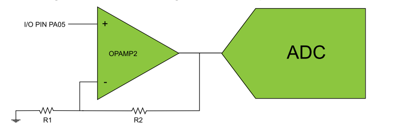
In this example application one of the OPAMPs is configured as a Non-Inverting
Programmable Gain Amplifier (PGA) with output internally connected to the ADC module
for signal sampling. The input signal is connected to the non-inverting (positive)
input while the inverting (negative) input and the output is connected in a closed
loop with an internal resistor ladder. The OPAMP2 positive input can be multiplexed
to I/O pin PA05, hence the input signal to be amplified must be connected to this
pin. The pin must also be configured as an input. The ADC input multiplexer needs to
be configured (MUXPOS = 0x1F) in order to use the OPAMP2 output as input. In this
example OPAMP2 is configured with R2/R1 = 1/3. Thus, the gain for this non-inverting
configuration is 1.33.
The ADC is configured as follows:
Single ended mode
VDDANA (3.3V) as reference
Perform conversion on software trigger
Generate interrupt when the result is ready
Downloading and Building the
Application
To clone or download this application from Github, go to the main page of this repository and then click Clone
button to clone this repository or download as zip file. This content can also be
downloaded using content manager by following these instructions.
Path of the application within the repository is
apps/opamp/opamp_adc_gain_amp/firmware.
To build the application, refer to the following table and open the project using its
IDE.
Non-inverting input of OPAMP2 is available on PA05 (Pin 15 on EXT1
connector).
Connect the input signal to this pin (Since the OPAMP gives gain of 1.33,
choose appropriate voltage to be connected at input of the OPAMP so that it
does not saturate the ADC result)
Connect the Debug USB port on the board to the computer using a micro USB
cable
Running the Application
Open the Terminal application (Ex.:Tera term) on the computer
Connect to the EDBG Virtual COM port and configure the serial settings as
follows:
Baud : 115200
Data : 8 Bits
Parity : None
Stop : 1 Bit
Flow Control : None
Build and Program the application using its IDE
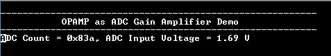
The console output will be as given below when the voltage at PA05 is 1.27V
The ADC result shows gain ie; output of OPAMP2 = 1.33 * 1.27V =
1.69V