
2.3.1 Graphics Getting Started Application on SAM9X60 Curiosity Development Board
Description
This graphics application demonstrates how to display the Microchip Graphics Quick Start project template to the Maxtouch 5-inch display on the SAM9X60 Curiosity Development board.
Key Highlights of SAM9X60 Curiosity Development Board
- LCD Interface.
- External Non-Volatile Memories like NAND, SD, and MicroSD card interfaces.
- Additional sensors can be interfaced using click boards through an on-board mikroBUS connector.
- Two mechanical programmable buttons.
- One User Input Switch and one RGB LED.
- UART, USB and CAN Interfaces.
- Raspberry pi connectors.
Modules/Technology Used
Peripheral Modules
- Flexcom
- LCDC Interface
- TC0 (TWI/I2C)
- MAXTOUCH Controller interface
Hardware Used
Software/Tools Used
This project has been verified to work with the following versions of software tools:
Refer Project Manifest present in harmony-manifest-success.yml under the project folder firmware/src/config/default to know the MPLAB® X IDE, MCC, libraries version.
Hardware Setup
- Connect the ribbon cable from the display to the J13 connector of the SAM9X60 Curiosity Development Board.
- Power up the board by connecting the USB cable to the USB port J1 on the SAM9X60 curiosity development board.
- Connect external debugger to J12.
Developing a Graphics Getting Started Demo
- Open MPLAB® X IDE from the main menu.
- Create a New Project by clicking
the New Project icon
 or
by selecting File -> New Project.
or
by selecting File -> New Project. - In the New Project window, under
Projectschoose Application Project(s). and click Next.

- In the Select Device
dialog window, fill in or select the information for below:
- Family: Fill configuration name as 32-bit MCUs (PIC32C/SAM).
- Device : From drop down list select SAM9X60.

- In the Select Compiler
window, for Compiler Toolchains select XC32 COMPILER, and Click
Next.

- Enter Project Location ,
Project Folder and Project Name. Click Finish

- From main menu, click on
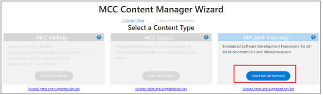
Tools -> Embedded -> MPLAB® Code Configurator or
click MCC button in the MPLAB® X IDE tool bar. It will launch Content
manger Wizard. Then, select MPLAB® Harmony.
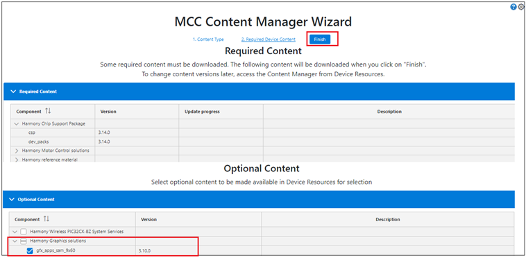
- In addition to the required
packages, download the optional packages gfx_sam9x60, bsp, csp, core, gfx,
dev_packs and then click Finish. Content download will take some time.
Wait till all the contents are downloaded.
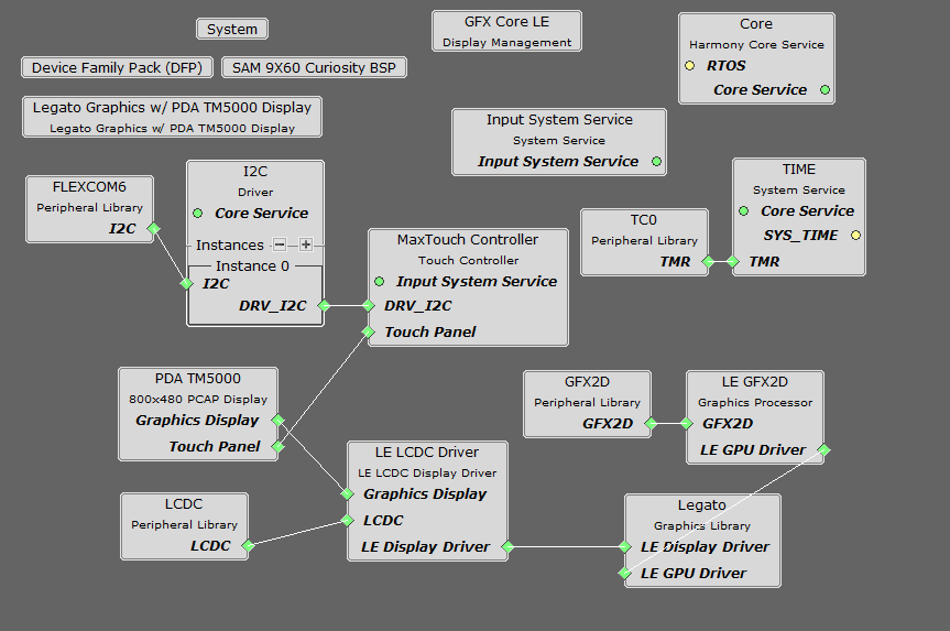
- Project graph will be displayed.
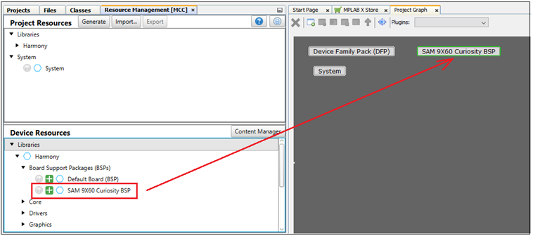
From device resource add Board Support Packages for SAM9X60 Curiosity
Kit BSP to Project Graph.
- From device resource add
Graphics -> Templates -> Legato Graphics w/PDA TM5000
Display to Project Graph. The user will be prompted to allow
auto-connection and auto-activation of several components. Click on Yes
for all of them except FreeRTOS.
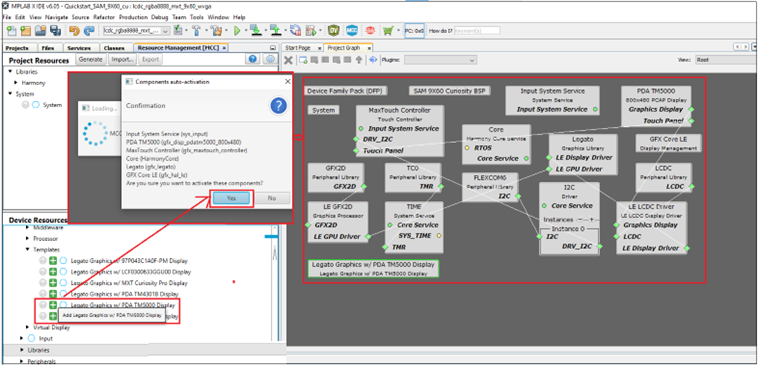
- Choosing the Legato Graphics w/PDA TM5000 Display template automatically populates rest of the project components. This can be seen in the way the project graph is setup and connected.
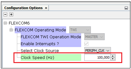
- In the project graph,
click on Flexcom6. In the Configuration Options window, select
clock speed as 100,000 (100KHz).
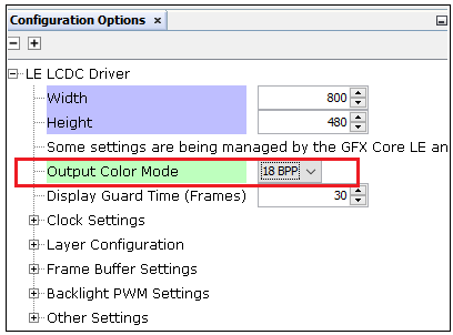
- In the project graph,
click on LE LCDC Driver. In the Configuration Options window,
select Output Color Mode as 18BPP.
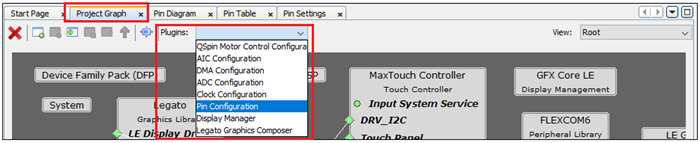
- From the project graph
window, plugins menu select Pin Configuration.
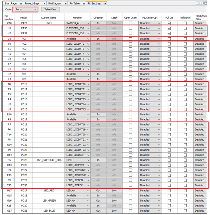
- The user can see that PA30 and
PA31 are set to FLEXCOM6. Enable pullups for those pins. Ensure all the pins are
configured as below:
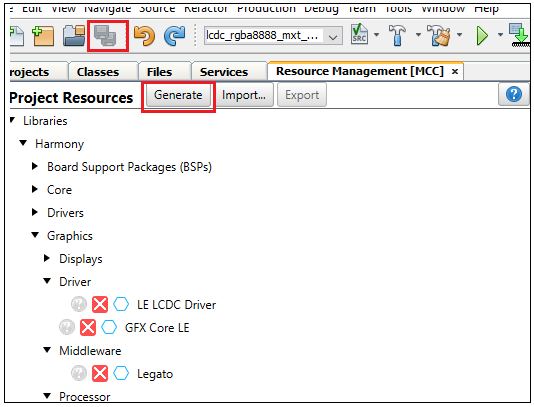
- Save all and then click
Generate Code. This will generate code for all the peripherals that
have been added in the project graph.
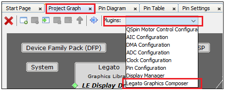
- Let us use Microchip Graphics
Composer(MGC) to design the graphics to be displayed on the LCD screen and
generate the legato library. From the Project graph -> plugin,
launch Legato Graphics Composer. (From next software update, this plugin
will be renamed to Microchip Graphics Composer).
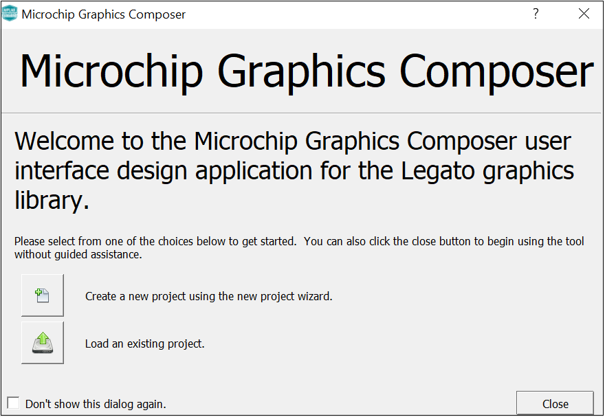
- From the window that pops-up,
click on Create a new project using the new project wizard.
- In the Display
Configuration window, choose WVGA (800x480) for Presets
and click on Apply. The user will see that the Width and Height are
updated. Click Next.
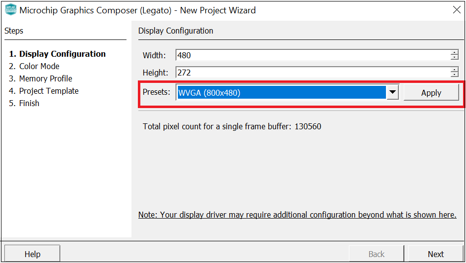
- For Color Mode -> select RGBA_8888. Click Next. For Memory Profile -> select MPU. Click Next. In the Project Template window, select the Start with a basic quickstart project template checkbox. Click Next and click Finish.
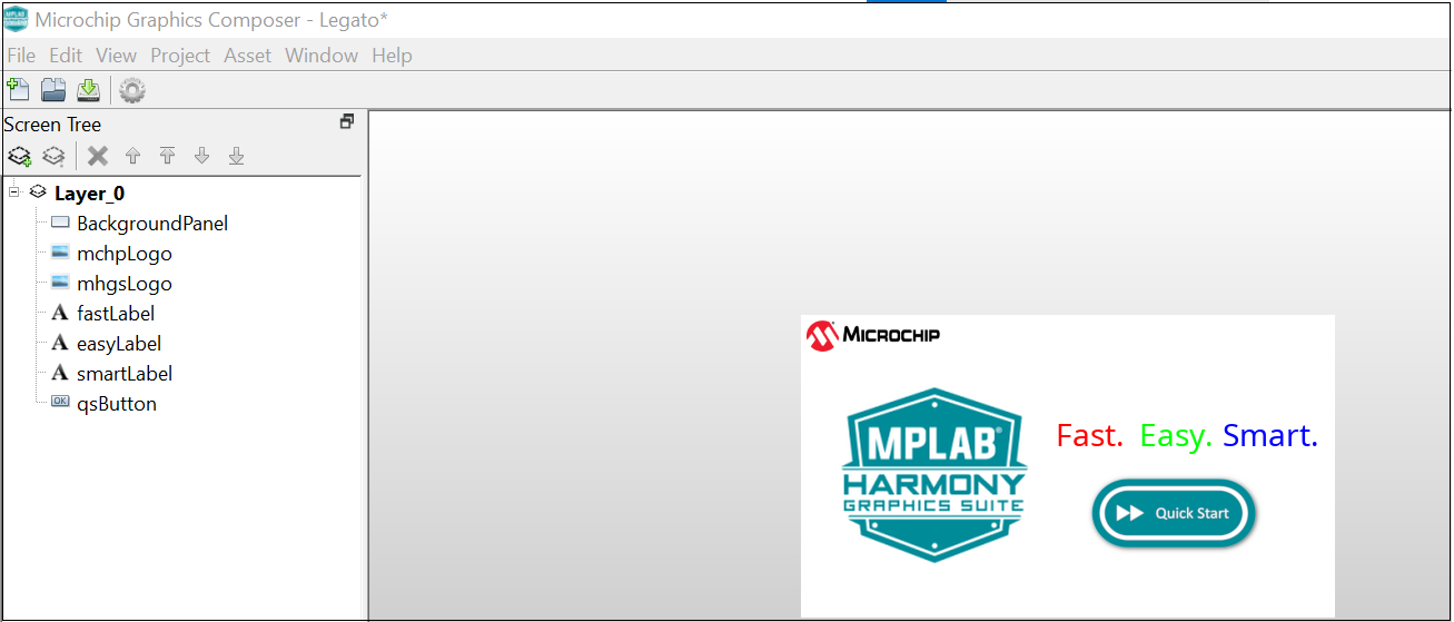
- The user will see the following
screen generated by the composer.
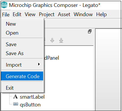
- After the graphics display is
composed, the user can generate the design files by clicking the Generate
Code from the File option in the main menu.
- The user can save the design
files by clicking on File from the main menu and selecting Save As.
Provide a filename with _design and save it in the (That way the next time MGC
is launched, the design file is automatically opened) and click Save.

- The user can exit Microchip Graphics Composer by clicking on Exit from File option in the main menu.
- From MCC, click on
Generate Code. This will generate code for the quickstart template
designed using Microchip Graphics Composer.
- Lastly change the following code.
In Legato -> renderer -> legato_renderer.c, add
proper section for no cache attribute as shown below:The
.region_nocachememory location is defined in the linker file and lets the linker know which memory region is to be used for scratch buffers.
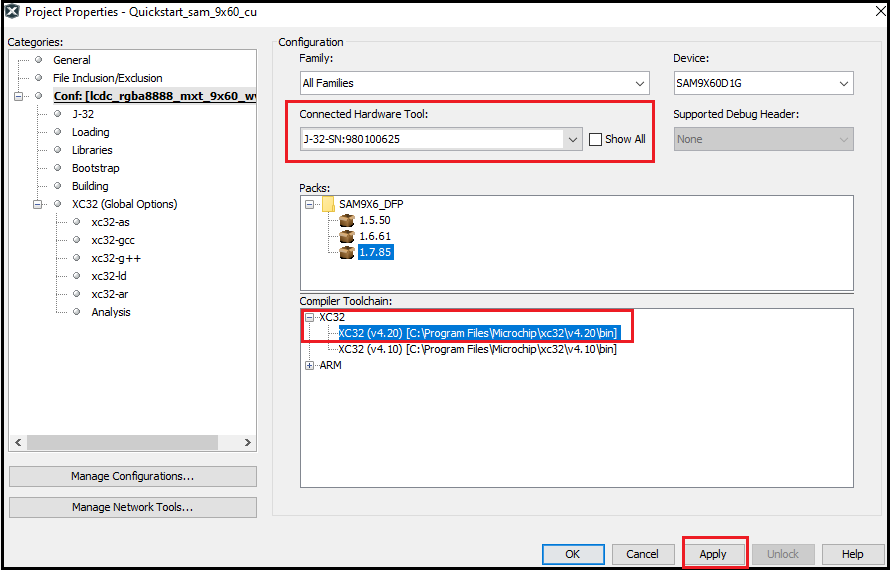
- Right click on the project
and click Properties. For Connected Hardware Tool -> select
connected hardware debugger used, for Compiler Toolchain -> select
XC32 and click Apply.
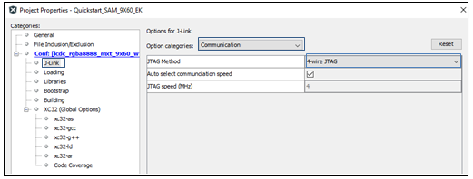
- From J-32 , in Option
categories choose Communication and for JTAG Method,
select 4-wire JTAG.
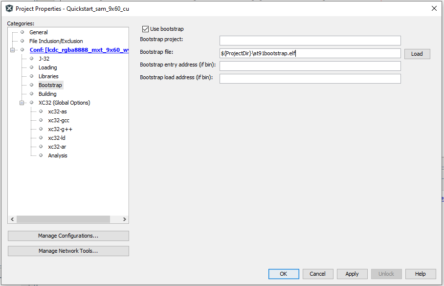
- Select Bootstrap for
Categories and select the Use Bootstrap checkbox. For bootstrap
file -> select the at91bootstrap elf file from the project
directory. Click on Apply and OK.
- Clean and build the project. The user should see a message on the output console that the project was successfully built. This completes the development of the basic graphics quickstart getting started application.
Debugging Application Project on MPLAB® X IDE
- Open the project (sam9x60_cu_graphics_getting_started/firmware/sam9x60_cu.X) in MPLAB® X IDE.
- Ensure SAM9X60D1G is selected as hardware tool to program/debug the application.
- Build the code and Debug the code by clicking on the Debug button in MPLAB® X IDE tool bar.
- Run the application by clicking Run button in MPLAB® X IDE tool bar.
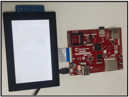
- The below legato quickstart template application will get displayed on the LCD connected with SAM9X60 Curiosity development board.

Running the Pre-built Harmony Application from SD Card
The pre-built application bin file can be programmed by following the below steps:
Steps to program the bin file on SD card:- Take a micro-SD Card formatted with FAT32 file system.
- Copy the boot.bin and harmony.bin files from sam9x60_cu_graphics_getting_started/hex folder to the micro-SD card using the PC.
- Insert the SD card to J3 on the SAM9X60 Curiosity development board.
- Press the reset button.
- It will display the below graphics getting started demo -a legato quickstart template application on the display connected with SAM9X60 Curiosity development board.
Comments
This application demo builds and works out of box by following the instructions above
in Running the Demo section. If the user needs to enhance/customize this
application demo, should use the MPLAB Harmony v3 Software framework. Refer links
below to setup and build the applications using MPLAB Harmony.
- How to Setup MPLAB Harmony v3 Software Development Framework
- How to Build an Application by Adding a New PLIB, Driver, or Middleware to an Existing MPLAB Harmony v3 Project
- Click Here for more graphics demos
- MPLAB® Harmony v3 is also configurable through MPLAB® Code Configurator (MCC)- Refer to the below links for specific instructions to use MPLAB® Harmony v3 with MCC.