
2.1.2 Ethernet Web Server Getting Started Application on SAMA7G54-EK Evaluation Kit
Description
This application demonstrates the ability of the MPLAB Harmony to configure demo board as TCP IP web server on SAMA7G54 Evaluation kit. The demo board configured as web server will host web-page stored in SDCARD. The web-page will be accessed through IP Address provided in debug window. From the web-page, LEDs on the demo board will be controlled. Temperature is read from the temp sensor on a Thermo 3 Click connected to the board using TWI/I2C protocol. The temperature value is also displayed on the web-page.
Key Highlights of SAMA7G54-EK Evaluation Kit
- External Non-Volatile Memories like QSPI, e.MMC and SD card interfaces.
- Additional sensors can be interfaced using click boards through an on-board mikroBUS connector.
- Two mechanical programmable buttons.
- One User Input Switch and one RGB LED.
- UART, USB and CAN Interfaces.
- Raspberry pi connectors.

Modules/Technology Used
Peripheral Modules:
- FLEXCOM
- TC0
- SDMMC
Hardware Used
- SAMA7G54-EK Evaluation Kit.
- SD Card.
- Thermo 3 Click.
- RJ45 Ethernet Cable.
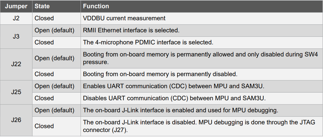
Jumper Settings
Software/Tools Used
This project has been verified to work with the following versions of software tools:
Refer Project Manifest present in harmony-manifest-success.yml under the project folder firmware/src/config/default to know the MPLAB® X IDE, MCC Plugin, libraries version.
Hardware Setup
- Connect RJ45 ethernet cable to the J5 Connector (Gigabit Ethernet port) of SAMA7G54-EK Evaluation Kit and to Router.
- Connect Thermo 3 click board to the J10 connector (mikroBUS socket) of SAMA7G54-EK Evaluation Kit.
- Power up the SAMA7G54-EK Evaluation Kit by connecting 5V/2A power adapter to J1 connector or by connecting micro-usb cable to J7 connector.
- Press the start (nSTART switch) button on the board.
- Connect the UART port (J24) on board to the computer using a micro-usb cable (to enable debug com port).
- Connect external JTAG debugger to
J27 or Onboard debugger micro-usb cable to J24. J24 will work as CDC COM Port as
well as Onboard debugger.
Developing a Ethernet Web Server Demo Application
- Open MPLAB® X IDE from the main menu.
- Create a New Project by clicking
the New Project icon
 or
by selecting File -> New Project.
or
by selecting File -> New Project. - In the New Project window, under
Projectschoose Application Project(s). and click Next.

- In the Select Device
dialog window, fill in or select the information for below:
- Family: Fill configuration name as 32-bit MCUs (PIC32C/SAM).
- Device : From drop down list select SAMA7G54.

- In the Select Compiler
window, for Compiler Toolchains select XC32 COMPILER, and Click
Next.

- Enter Project Location ,
Project Folder and Project Name. Click Finish

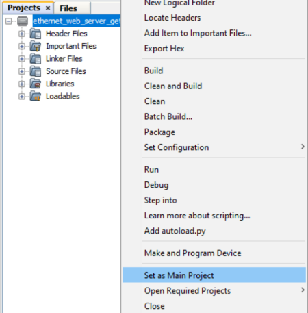
- This creates an empty project and
set this project as main project. If there are other projects open in the
project explorer window, set this project as main project by right
clicking on the project, choose Set as Main Project.
- Once the project is created,
MCC will be automatically launched. (To launch MCC manually,
from main menu, click on Tools -> Embedded -> MPLAB® Code
Configurator or click MCC button
 in
the MPLAB® X IDE tool bar.) It will launch Content manger Wizard. Then
click Select MPLAB Harmony.
in
the MPLAB® X IDE tool bar.) It will launch Content manger Wizard. Then
click Select MPLAB Harmony.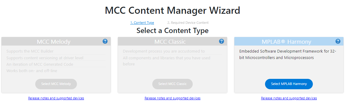
- In addition to the required
packages(csp,dev_packs), download the optional packages
bsp, core, net, wolfssl and then click
Finish. Content download will take some time. Wait till all the
contents are downloaded.


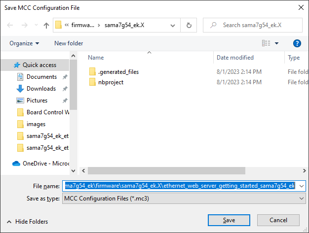
- Once the download is complete,
click Save in Save MCC Configuration file window.
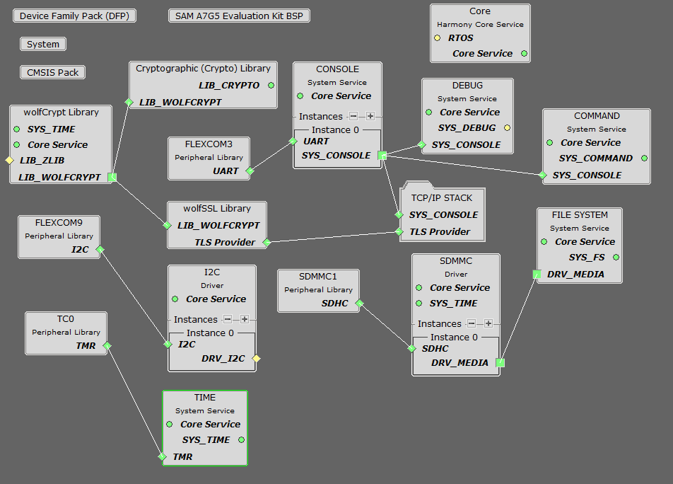
- A project graph will be
displayed. From Device Resources window, click add button
 to
add Board Support Packages for SAMA7G5 Evaluation kit BSP to Project
Graph.
to
add Board Support Packages for SAMA7G5 Evaluation kit BSP to Project
Graph.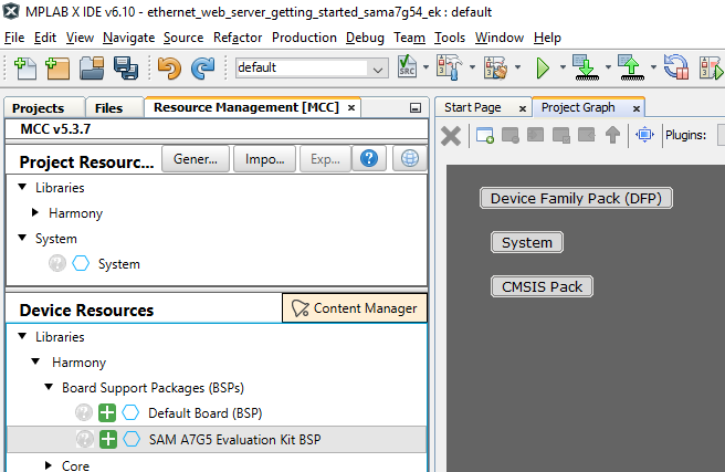
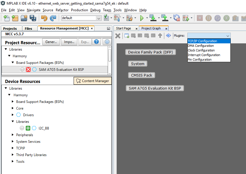
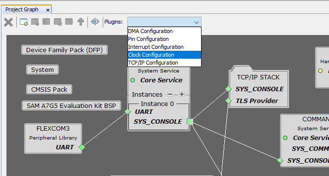
- In Project Graph, Select
TCP/IP Configuration from plugins drop-down list.
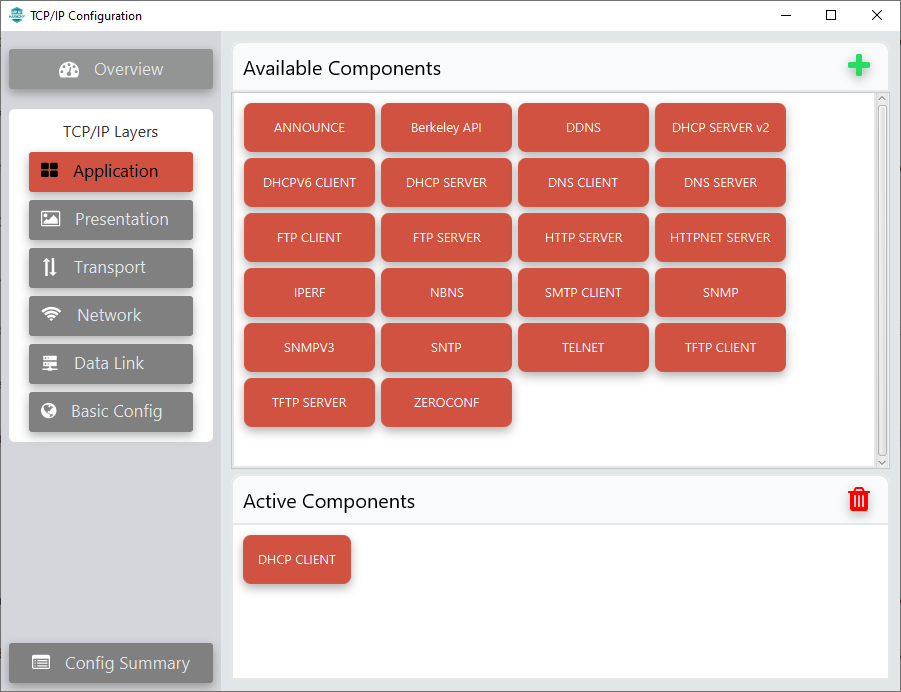
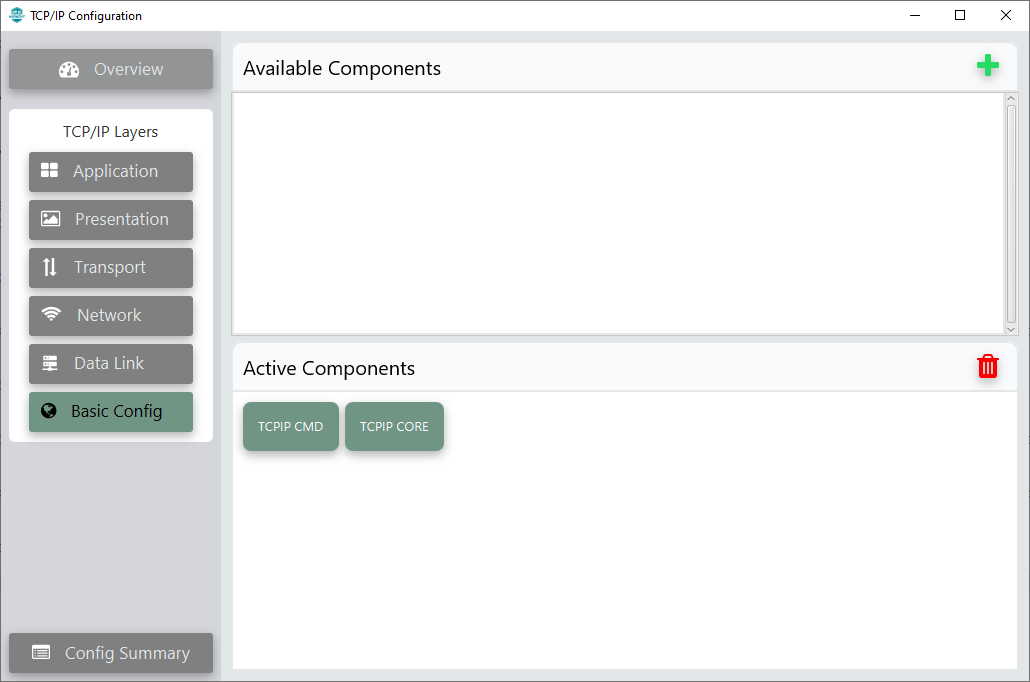
- TCP/IP Configuration
window will be displayed. Click Application in TCP/IP Layers on the left
side pane.
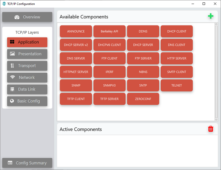
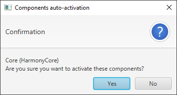
- To add DHCP CLIENT to
Active Components window, drag and drop it from Available
Components. Click Yes for adding Harmony Core.
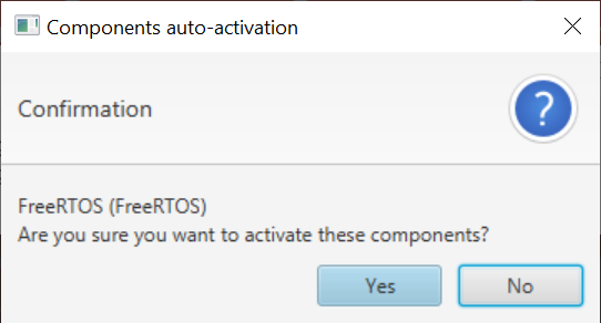
- Click No for FreeRTOS
component. This example is a Bare metal project.
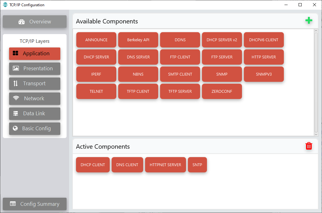
- DHCP CLIENT is moved to
Active Components window.
- Similarly add DNS CLIENT,
HTTPNET SERVER and SNTP to Active Components
window.
- Click Presentation in
TCP/IP Layers on the left side pane.
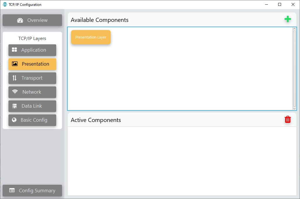 Add Presentation Layer to Active Components window by dragging and dropping it from Available Components window.
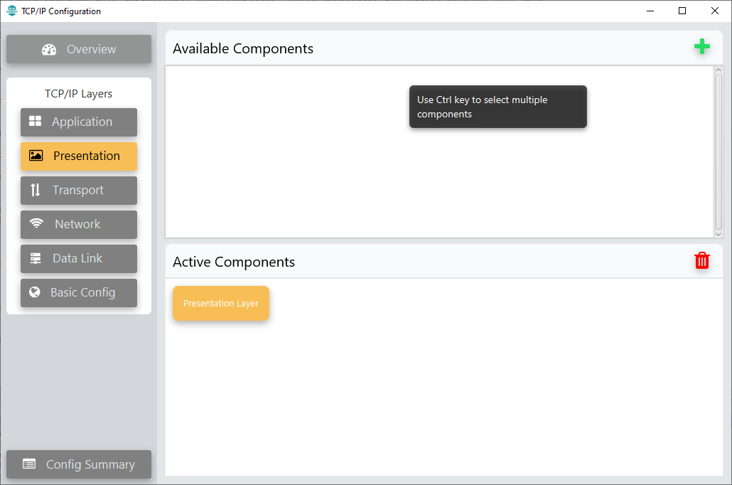
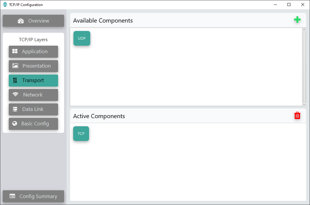
- Click Transport in TCP/IP
Layers on the left side pane.
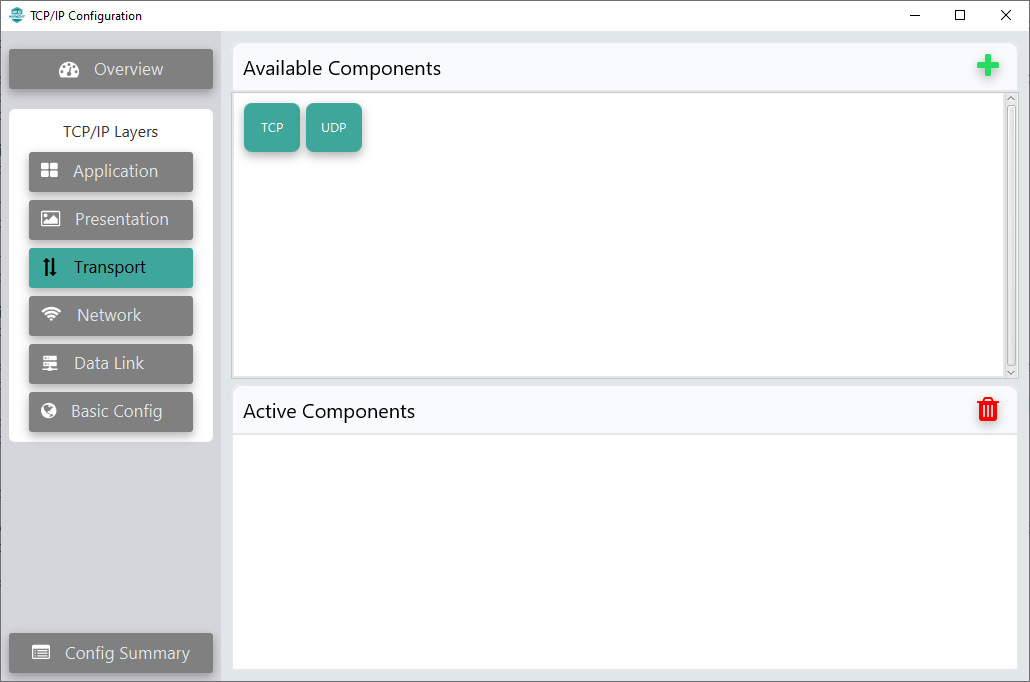
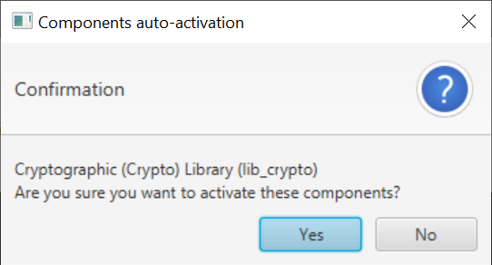
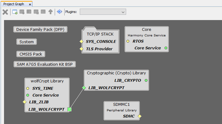
- Add TCP to Active Components window by dragging and dropping it from Available Components window. This will add Crypto Library also to the project.
- Click Yes to add Crypto Library. The wolfCrypt Library will
be added to the project.
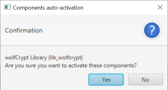
- Click Yes to add
wolfCrypt Library.
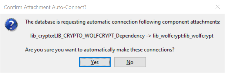
- Click Yes to connect Crypto Library and wolfCrypt Library
in project graph.
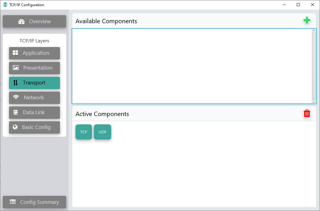
- TCP added to project.
- Add UDP to Active Components window by dragging and dropping from
Available Components window.
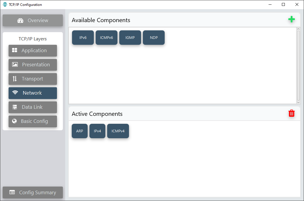
- Click Network in TCP/IP
Layers on the left side pane.
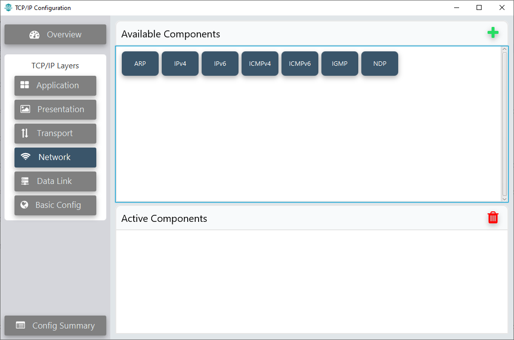
- Add IPv4, ARP and
ICMPv4 to Active Components window by dragging and dropping
them from Available Components window.
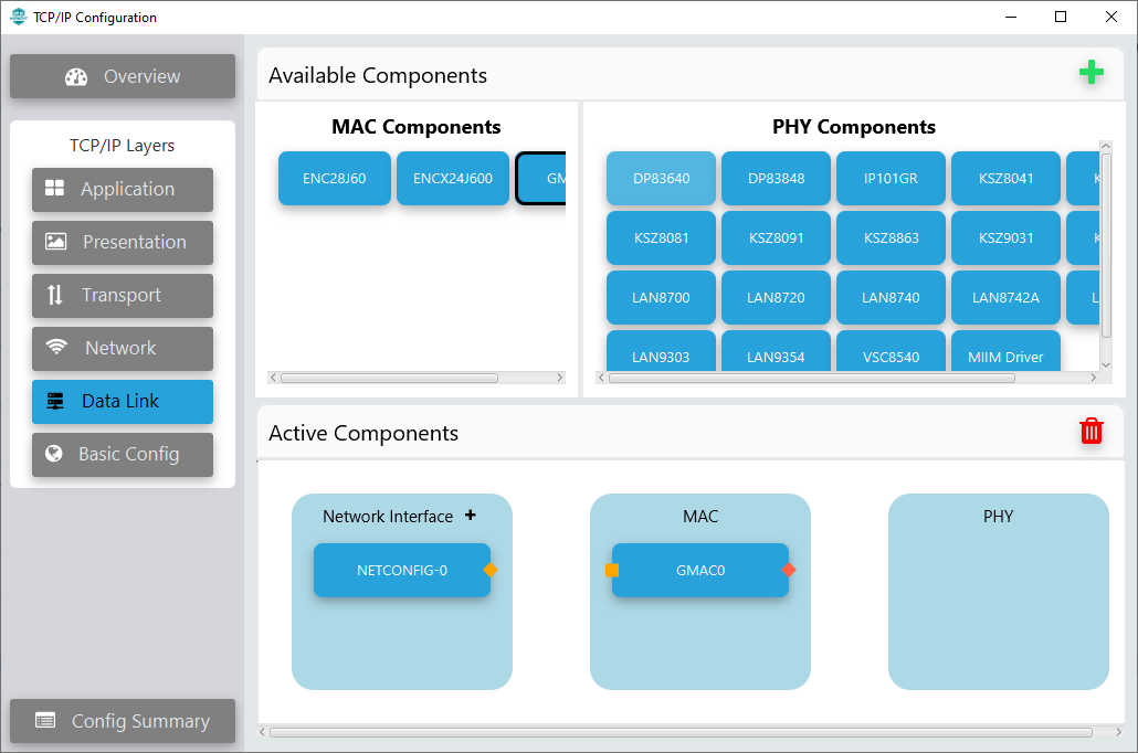
- Click Data Link in TCP/IP
Layers on the left side pane.
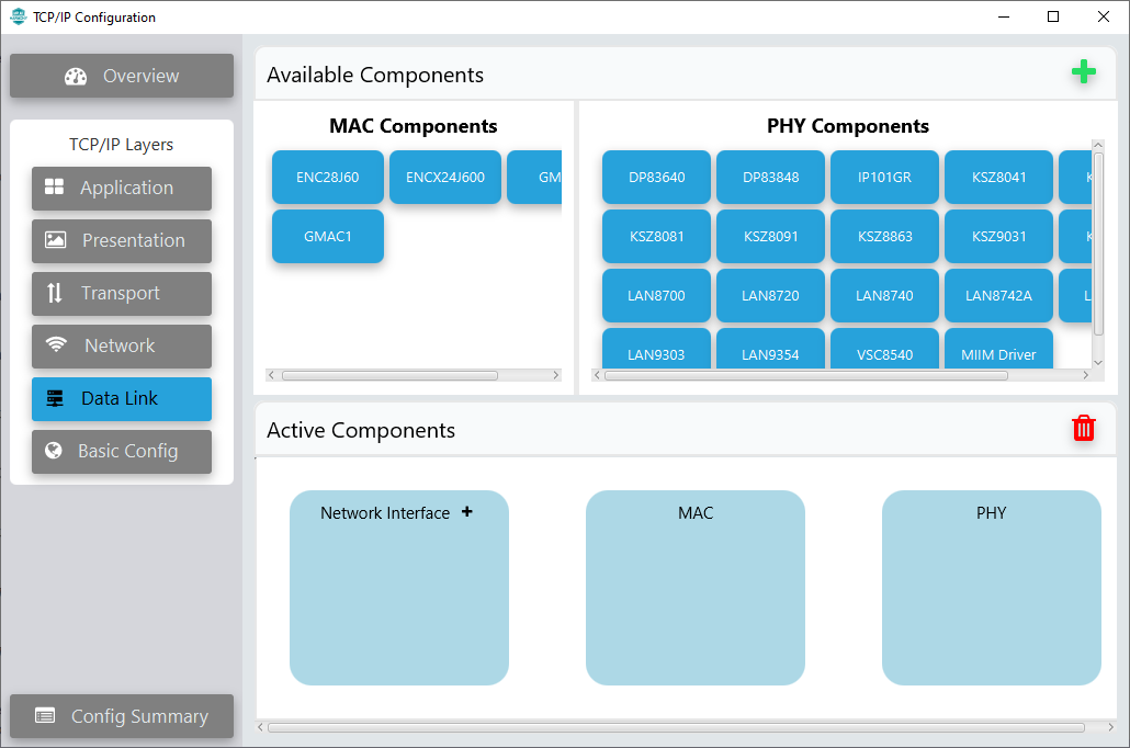
- Click
 next to Network Interface in Active Components window to add an
Interface. This will add NETCONFIG-0 to Network Interface section
in Active Components window.
next to Network Interface in Active Components window to add an
Interface. This will add NETCONFIG-0 to Network Interface section
in Active Components window.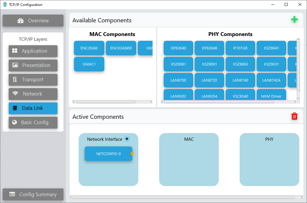
- Add GMAC0 to MAC
section in Active Components window by dragging and dropping from MAC
Components window.
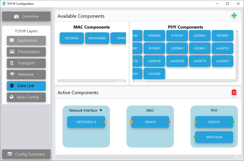
- Add KSZ9131 and MIIM
Driver to PHY section in Active Components window by drag
and drop from PHY Components window.
- Connect NETCONFIG-0 with
GMAC0 and GMAC0 with KSZ9131 in Active
Components window by clicking and dragging the
 or
or
 button.
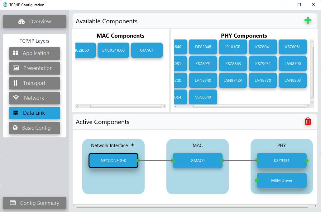
- Click Basic Config in
TCP/IP Layers on the left side pane.
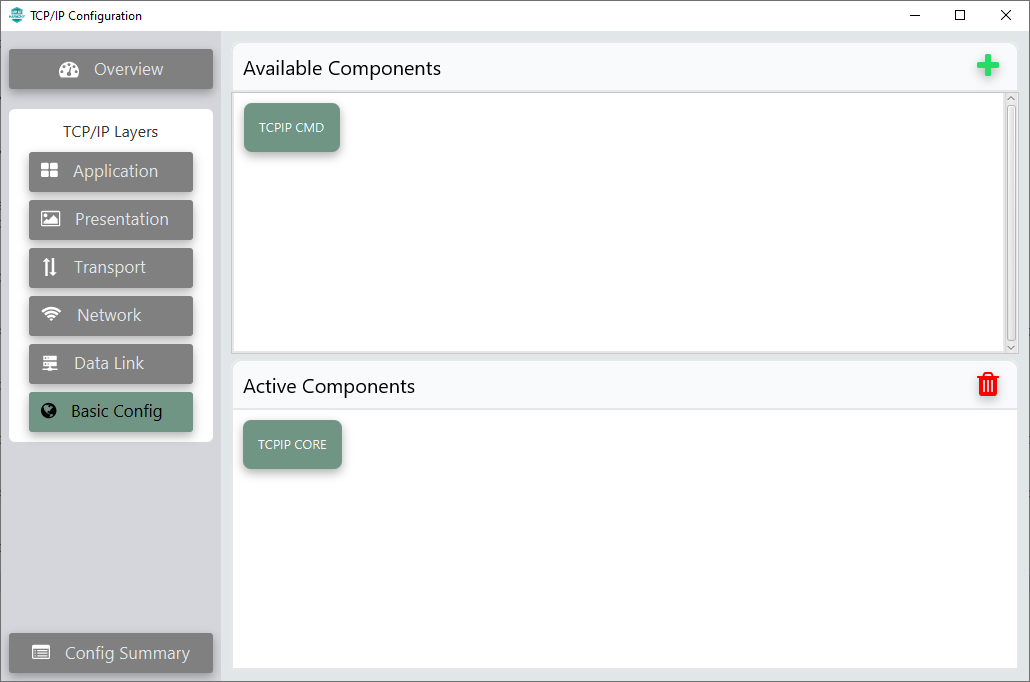
- Add TCPIP CMD to Active
Components window by dragging and dropping from Available
Components window.
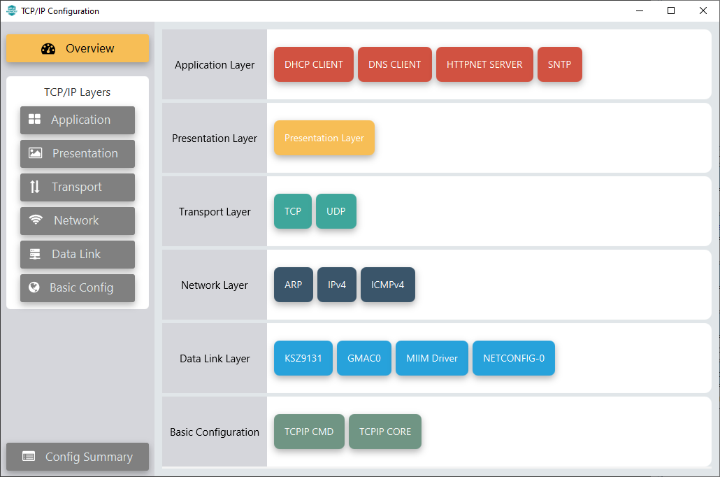
- Click Overview on the left
side pane to see the complete configuration.
- Click Config Summary on
the left side pane to see the summary of configuration. The missing mandatory
and optional components will be listed here.
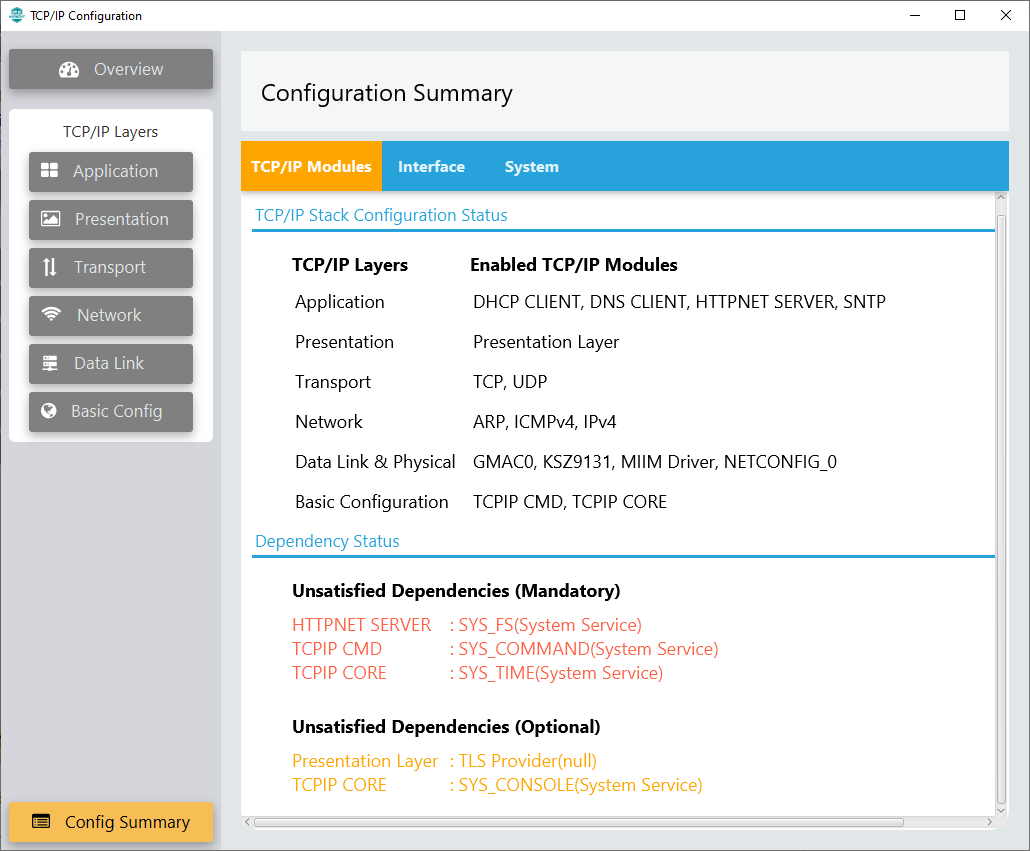
- Add Harmony components listed in
Unsatisfied Dependencies.
- Close TCP/IP Configuration window.
- In Project Graph, select Root in View tab and add all Unsatisfied Dependencies.
- To store webpages is needed a SDCARD. To access SDCARD, the user needs to enable SDMMC module in project.
- From Device Resources window, expand Peripherals and expand SDMMC to view SDMMC list.
- Click add button to
add SDMMC1 to Project Graph.
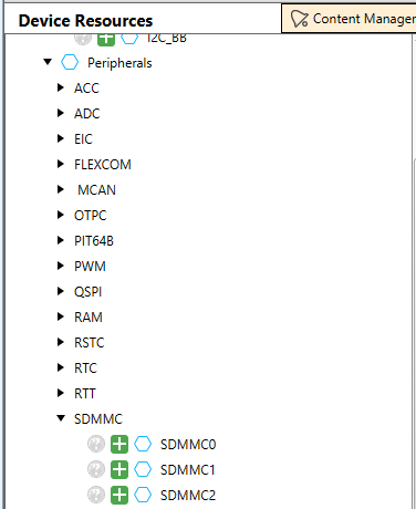
- SDMMC1 added to Project
Graph window.
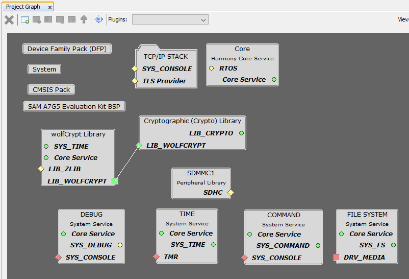
- From Device Resources window, expand System Services to view the list.
- Click add button to
add COMMAND, DEBUG, TIME and FILE SYSTEM to
Project Graph.
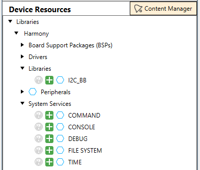
- COMMAND, DEBUG,
TIME and FILE SYSTEM are added to Project Graph window.
- Add SYS_CONSOLE
dependency.
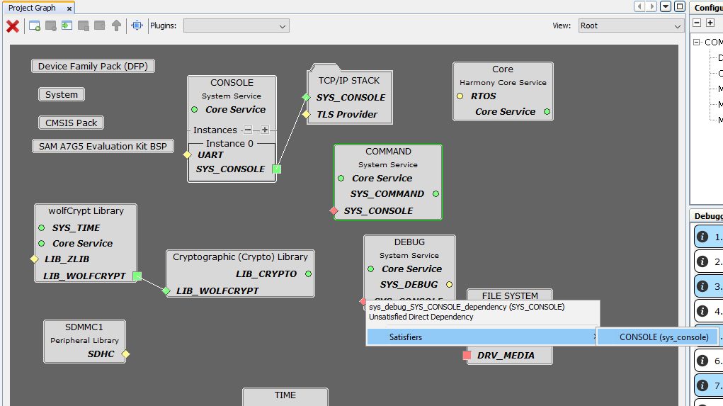
- Right Click on SYS_CONSOLE button
 on TCP/IP STACK box.
 - Select Satisfiers → CONSOLE.
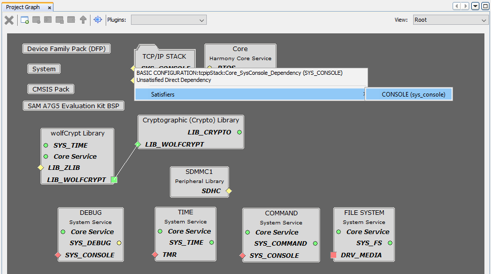
- Right Click on SYS_CONSOLE button
- Add COMMAND and DEBUG System
Service to CONSOLE.
- Right Click on SYS_CONSOLE button on DEBUG box.
- Select Satisfiers → CONSOLE.
- Right Click on SYS_CONSOLE button on COMMAND box.
- Select Satisfiers → CONSOLE.
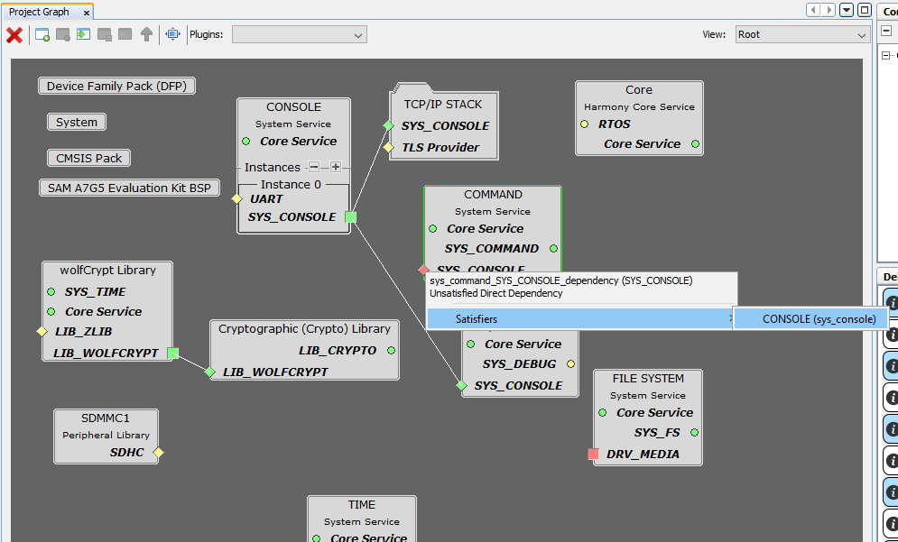
- Right Click on SYS_CONSOLE button
- Add SDHC consumers.
- Right Click on SDHC button on SDMMC1 box.
- Select consumers → SDMMC.
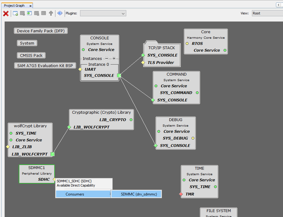
- Right Click on SDHC button
- Add SDMMC consumers.
- Right Click on DRV_MEDIA button
 on SDMMC box.
 - Select consumers → FILE SYSTEM.
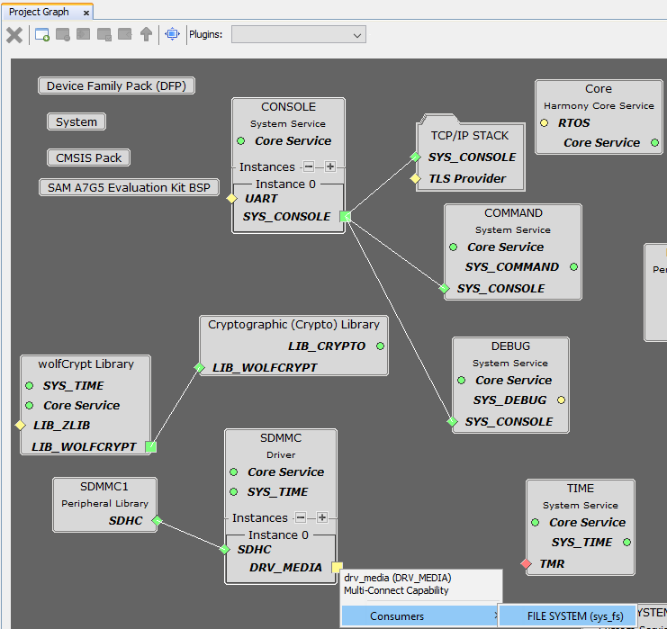
- Right Click on DRV_MEDIA button
- Add TIME satisfiers.
- Right Click on TMR button on TIME box.
- Select Satisfiers → TC0.
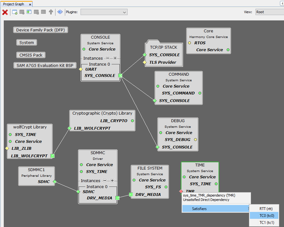
- Right Click on TMR button
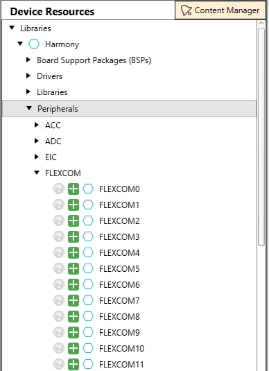
- From Device Resources window, expand Peripherals and expand FLEXCOM to view FLEXCOM list.
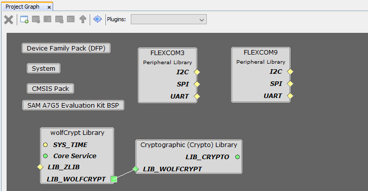
- Click add button to
add FLEXCOM3 and FLEXCOM9 to Project Graph.
- In SAMA7G54-EK Evaluation Kit,
Debug UART is connected to FLEXCOM3 peripheral module.
- To add UART consumers, Right Click on UART button on FLEXCOM3 box.
- Select consumers → CONSOLE.
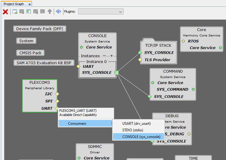
- To add UART consumers, Right Click on UART button
- In SAMA7G54-EK Evaluation Kit,
Thermo 3 click board is connected to MikroBUS 1 Slot. I2C communication Protocol
is required to access Thermo 3 click board. The I2C/TWI lines of MikroBUS 1 Slot
are connected to FLEXCOM9 peripheral module.
- To add I2C consumers, Right Click on I2C button on FLEXCOM9 box.
- Select consumers → I2C.
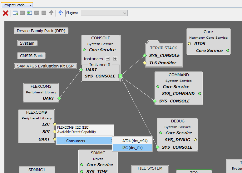
- To add I2C consumers, Right Click on I2C button
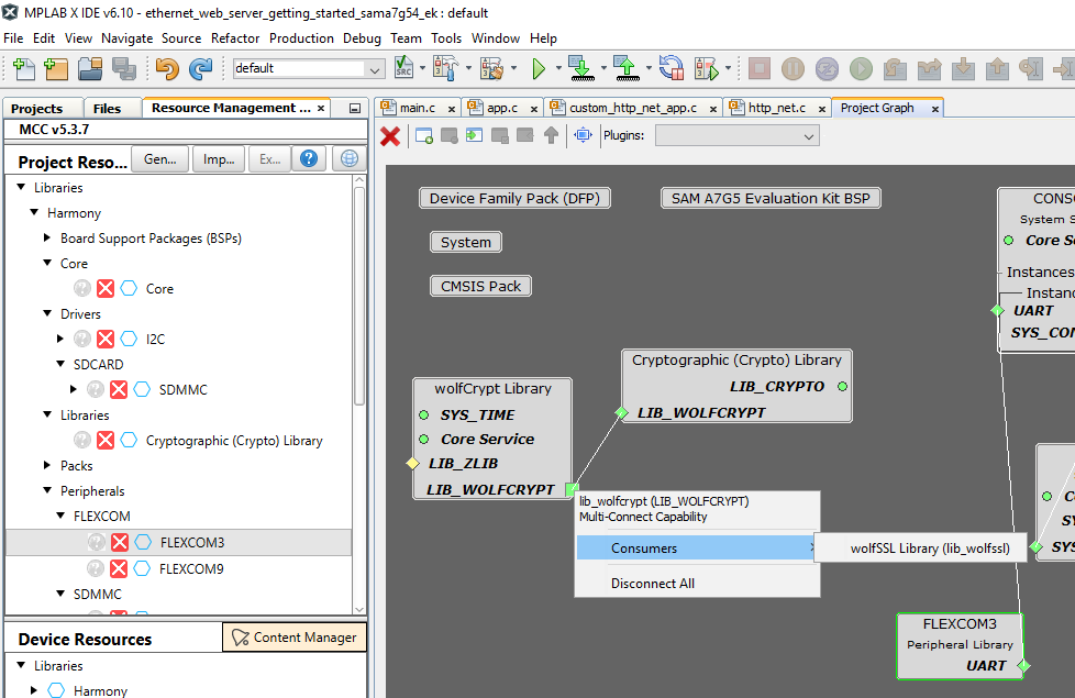
- Add wolfCrypt Library
consumers.
- Right Click on LIB_WOLFCRYPT button on wolfCrypt Library box.
- Select consumers → wolfSSL Library.
- Right Click on TLS Provider button on TCP/IP STACK box.
- Select Satisfiers → wolfSSL Library.
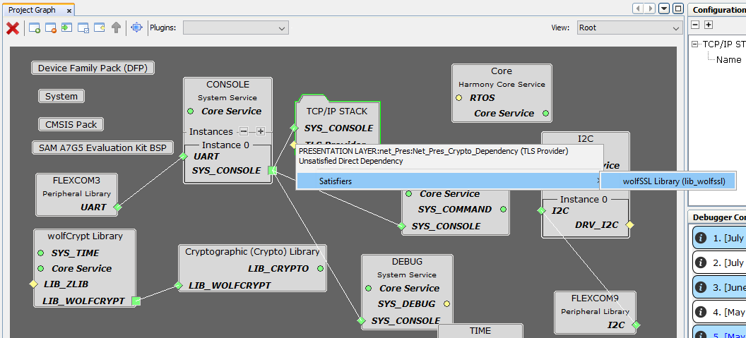
- Right Click on LIB_WOLFCRYPT button
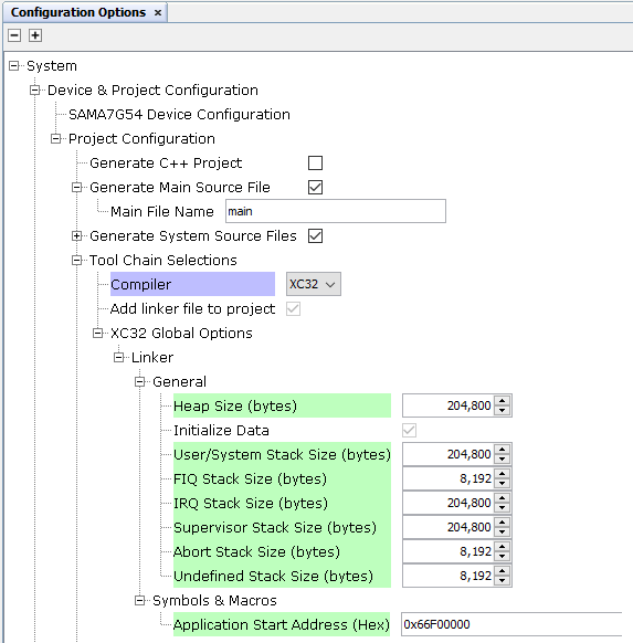
- Update the System Heap
size and all other Stack Size.
- Select the System in the Project Graph window.
- In Configuration Options window, update the System Heap size and all other Stack Size as shown in the image below.
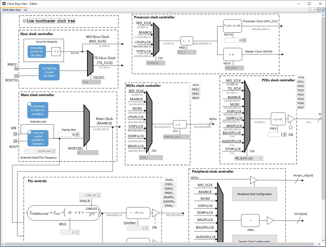
- Start Clock Configuration
from Plugins drop-down menu.
- Verify the clock
configuration. The application demo can work with default clock
configuration.
- Verify the Processor Clock (CPU_CLK) is 800,000,000 Hz.
- Verify the Master Clock (MCK0) is 200,000,000 Hz.
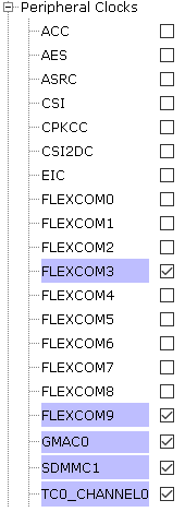
- Verify the Peripheral Clocks are enabled for FLEXCOM3, FLEXCOM9,
GMAC0, SDMMC1 and TC0. Select the System in the Project
Graph window. In Configuration Options, expand
Clock then expand Peripheral Clocks.
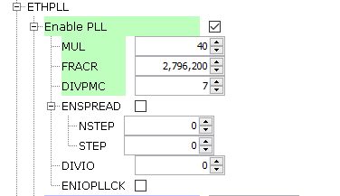
- GMAC0 requires 125,000,000 Hz clock frequency. ETHPLL
should be used as clock source. To Enable ETHPLL, select the
System in the Project Graph window. In
Configuration Options, expand Clock then expand
ETHPLL. Click on the check box of Enable PLL and
update the value as shown below.
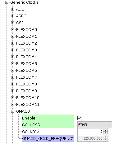
- Enable GMAC0 clock. Select the System in the Project Graph window. In Configuration Options, expand Clock then expand Generic Clocks.
- Expand GMAC0 and click on Enable check box. Update
GCLKCSS as ETHPLL.
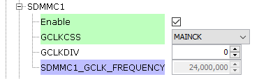
- Enable SDMMC1 clock. Select the System in the Project Graph window. In Configuration Options, expand Clock then expand Generic Clocks.
- Expand SDMMC1 and Click on Enable check box. Update
GCLKCSS as MAINCK.
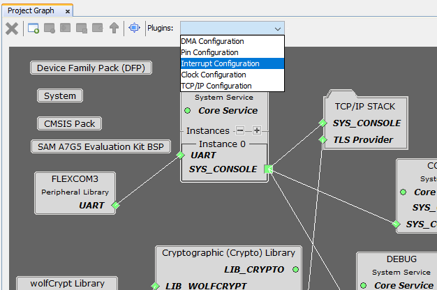
- Start Interrupt
Configuration from Plugins drop-down menu.
- Verify whether FLEXCOM3, FLEXCOM9, GMAC0, SDMMC1 and
TC0_CH0 interrupt is enabled.


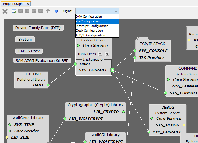
- Start Pin Configuration
from Plugins drop-down menu.
- Refer to the SAMA7G54-EK User's Guide for the UART pins.
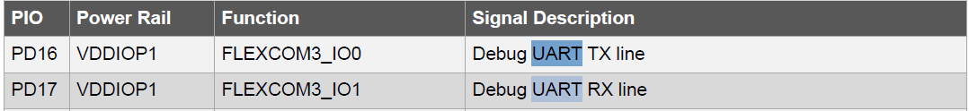
- Configure the pins for UART as shown below.

- Refer to the SAMA7G54-EK User's Guide for TWI pins.

- Configure the pins for TWI as shown below.

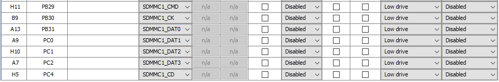
- Configure the pins for SDMMC1 as shown below.
- Refer to Gigabit Ethernet Interface Schematic in SAMA7G54-EK
User's Guide for the GMAC0 pins.
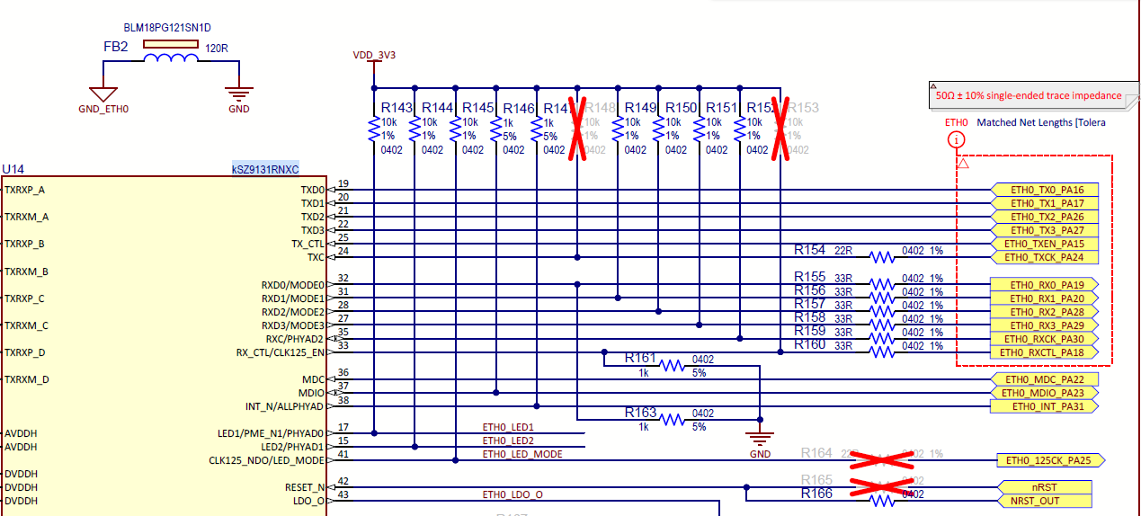
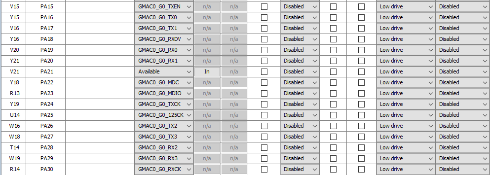
- Configure the pins for GMAC0 as shown below.
- Refer to the SAMA7G54-EK User's Guide for the UART pins.
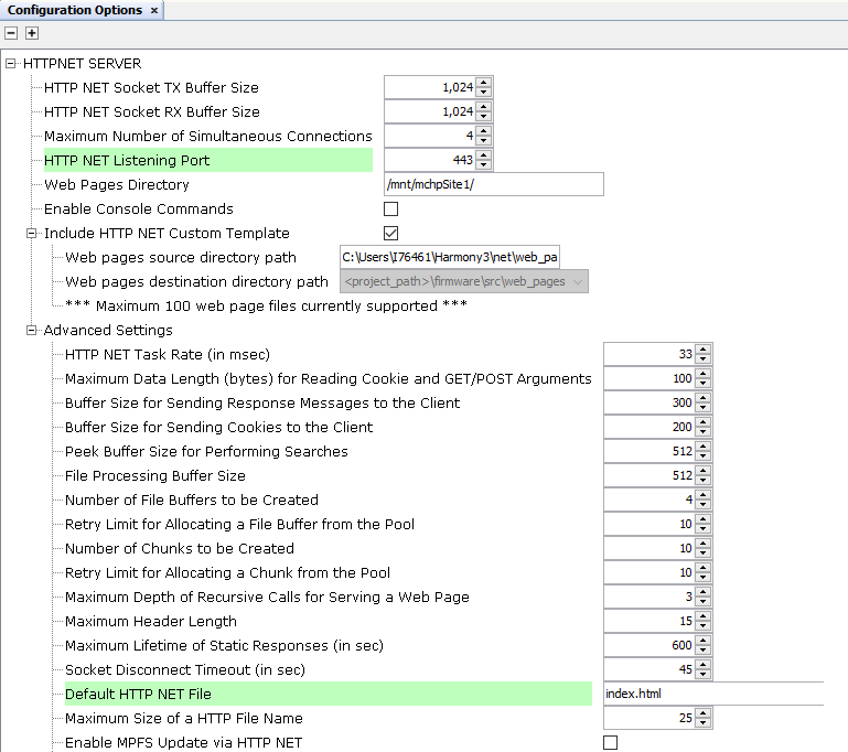
- Update HTTPNET SERVER
Listening port and default HTTP NET file.
- In Project Graph window, select APPLICATION LAYER from the list in View tab.
- Click on HTTPNET SERVER box in Project Graph.
- In Configuration Options, go to HTTPNER SERVER and expand Advanced Settings. Update Default HTTP NET file as index.html and update HTTP NET Listening Port as 443.
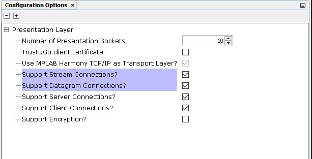
- Enable Encryption setting.
- In Project Graph window, select PRESENTATION LAYER from the list in View tab.
- Click on Presentation Layer box in Project Graph.
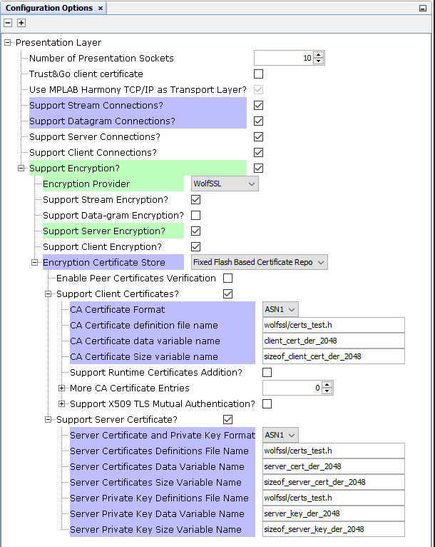
- In Configuration Options window, Enable Support
Encryption? by clicking on the check box.
- In Configuration Options window, expand Support Encryption? Update Encryption Provider as WolfSSL from list and enable Support Server Encryption? by clicking on the check box.
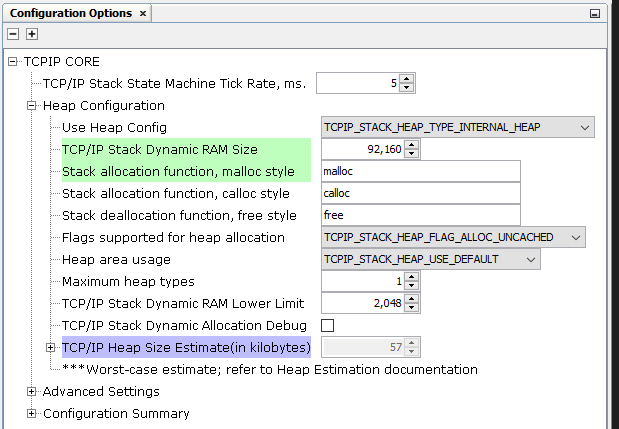
- Update TCP/IP stack Dynamic
RAM Size to 92160.
- In Project Graph window, select BASIC CONFIGURATION from the list in View tab.
- Click on TCPIP CORE box in Project Graph.
- In Configuration Options, expand Heap Configuration and
update TCP/IP stack Dynamic RAM Size to 92160.
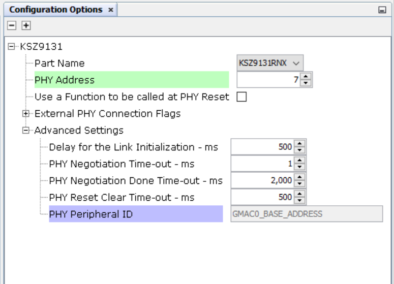
- Update KSZ9131 PHY Address
to 7.
- In Project Graph window, select DATA LINK LAYER from the list in View tab.
- Click on KSZ9131 box in Project Graph.
- In Configuration Options window, in KSZ9131 Update PHY
Address to 7.
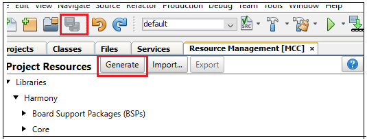
- Save all and then click
Generate Code. This will generate code for all the Device Resource
that have been added in the project graph.
- Up to this point in the project
creation process, the user used MPLAB Code Configurator (MCC) to configure and
generate code to initialize the device (SAMA7G54).Refer initialization.c file in project_directory/src/config to find that all the device resource added in the project graph got initialized. All that is left is for the user to write the application code in the app.c file. Documentation for each of the peripheral libraries or driver libraries can be accessed as follows:
- Peripheral libraries APIs can be accessed as a HTML file (.html) from the Harmony 3 Framework path. (/framework_path/csp/docs/index.html).
- BSP libraries APIs can be found in bsp.h.
- TCP/IP Stack APIs can be accessed as a HTML file (.html) from the Harmony 3 Framework path. (/framework_path/net/docs/index.html).
- APIs used for this application
are as follows:
- LED_GREEN_On
- LED_GREEN_Off
- LED_Red_On
- LED_Red_Off
- LED_Blue_On
- LED_Blue_Off
- FLEXCOM9_TWI_CallbackRegister
- FLEXCOM9_TWI_Write
- FLEXCOM9_TWI_IsBusy
- FLEXCOM9_TWI_Read
- SYS_FS_Mount
- TCPIP_STACK_Status
- SYS_CONSOLE_PRINT
- SYS_CONSOLE_MESSAGE
- TCPIP_STACK_NumberOfNetworksGet
- TCPIP_STACK_NetAddress
- TCPIP_STACK_NetNameGet
- TCPIP_STACK_NetIsReady
- TCPIP_STACK_IndexToNet
- Sample code can be found in app.c in project_directory/src folder.
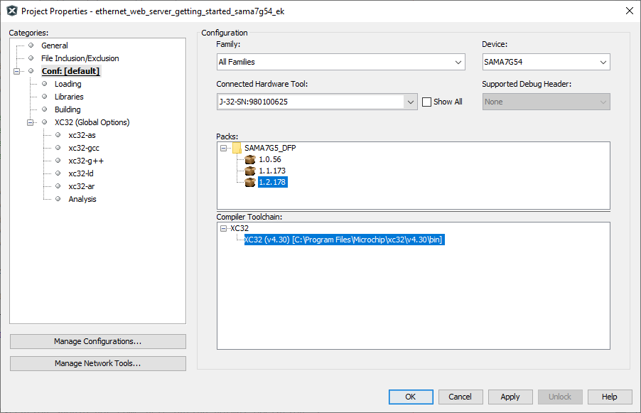
- Right click on the project and
click Properties. For Connected Hardware Tool -> select
connected hardware debugger used, for Compiler Toolchain -> select
XC32 and click Apply.
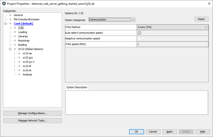
- From J-32/J-Link, In Option
categories choose Communication and for JTAG Method,
select 4-wire JTAG.
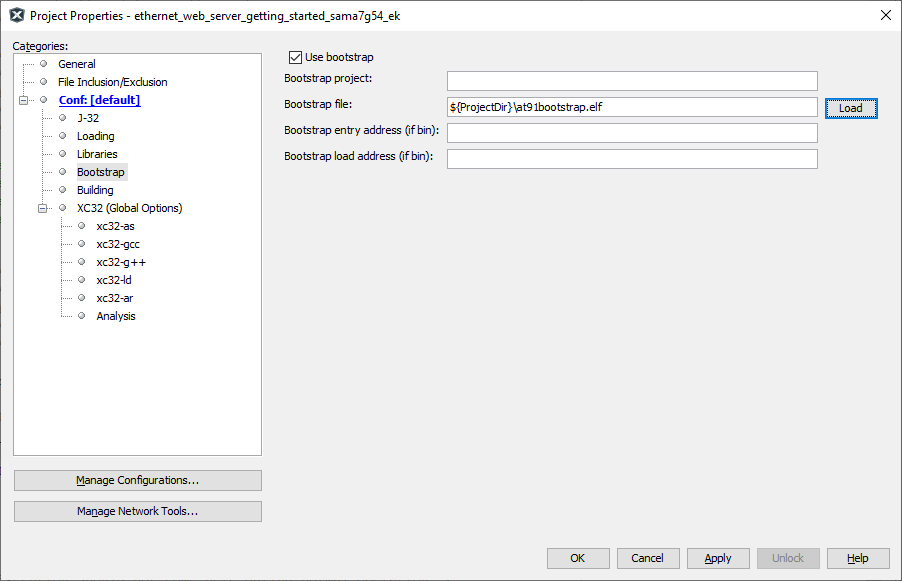
- Select bootstrap from
Categories and select the Use Bootstrap checkbox. For
bootstrap file -> select the at91bootstrap.elf file from
the project directory. Click on Apply and OK.
- By default, MPLAB X only
produces ELF and Hex format output files. To generate application
output in binary format, a post build step needs to be added to the project
properties. To do this, right click on project and select properties,
select building, click the check box Execute this line after
build, then enter the below command.
${MP_CC_DIR}/xc32-objcopy -O
                            binary ${DISTDIR}/${PROJECTNAME}.${IMAGE_TYPE}.elf
                            ${DISTDIR}/harmony.bin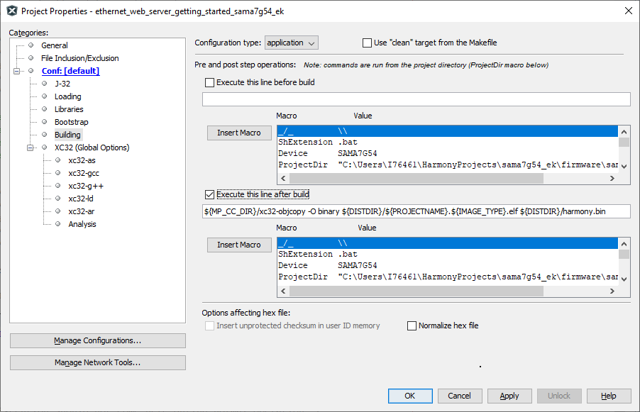
Click on Apply and OK.
- Clean and build the project. The user should see a message on the output console that the project was successfully built. This completes the development of the Ethernet web server getting started application.
- The harmony.bin binaries will be available at ./firmware/sama7g54_ek.X/dist/default/production.
Debugging Application Project on MPLAB® X IDE
- Open the project (sama7g54_ek_ethernet_web_server_getting_started/firmware/sama7g54_ek.X) in MPLAB® X IDE.
- In the project properties, ensure SAMA7G54 is selected as the Device and for Connected Hardware Tool, select the hardware debugger connected to the board to program/debug the application.
- Build and debug the code by clicking on the Debug button in MPLAB® X IDE tool bar.
- Run the application by clicking the Run button in MPLAB® X IDE tool bar.
- Ensure Console Serial
communications between the Host PC and the SAMA7G54-EK Evaluation Board take
place through UART port J24. A terminal emulation program running on the Host PC
communicates with the SAMA7G54-EK Evaluation Kit UART port. Ensure the terminal
emulation program (Eg: Tera term) is configured to the COM port and settings
are:
- Speed: 115200
- Data: 8
- Parity: None
- Stop Bits: 1
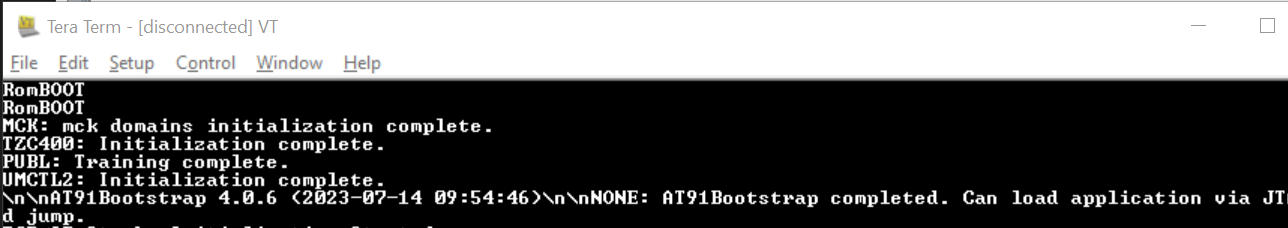
- Once the board is powered up, the
user will see the Blue LED turn ON. The following message is displayed on the
console:
Running the Pre-built Harmony Application from SD Card
The pre-built application bin file can be programmed by following the below steps.
Steps to program the bin file on SD card:
- Take an SD Card formatted with FAT32 file system.
- Copy the boot.bin, harmony.bin files from the project_directory/hex folder to the SD card.
- Copy the webpage files from sama7g54_ek/sama7g54_ek_ethernet_web_server_getting_started\firmware/src/webpage folder to the SD card.
- Insert the SD card to J4 on the SAMA7G54-EK Evaluation Kit.
harmony.bin
Steps to run the bin file from SD card:
- Press the reset button.
- The following debug messages will be
displayed on the console. Note the IP Address.
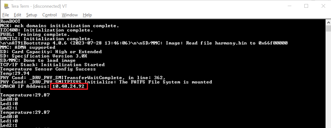
- Enter the IP Address (Example:
https://10.40.24.92) in web browser and press enter. The following webpage will be
displayed on the browser.

- Control each LED from web-page and view LED status updated. View the temperature displayed on the web-page.
Comments
This application demo builds and works out of the box by following the instructions above in Running the Demo section. If the user needs to enhance/customize this application demo, should use the MPLAB Harmony v3 Software framework. Refer links below to setup and build the applications using MPLAB Harmony.
- How to Setup MPLAB Harmony v3 Software Development Framework (DS90003232).
- How to Build an Application by Adding a New PLIB, Driver, or Middleware to an Existing MPLAB Harmony v3 Project (DS90003253).
- MPLAB® Harmony v3 is also configurable through MPLAB® Code Configurator (MCC)- Refer to the below links for specific instructions to use MPLAB® Harmony v3 with MCC.