5.2 Application flow
Push data in application context refers to the data that is automatically transmitted from the end-devices to the coordinator on a regular basis without requiring any user intervention.
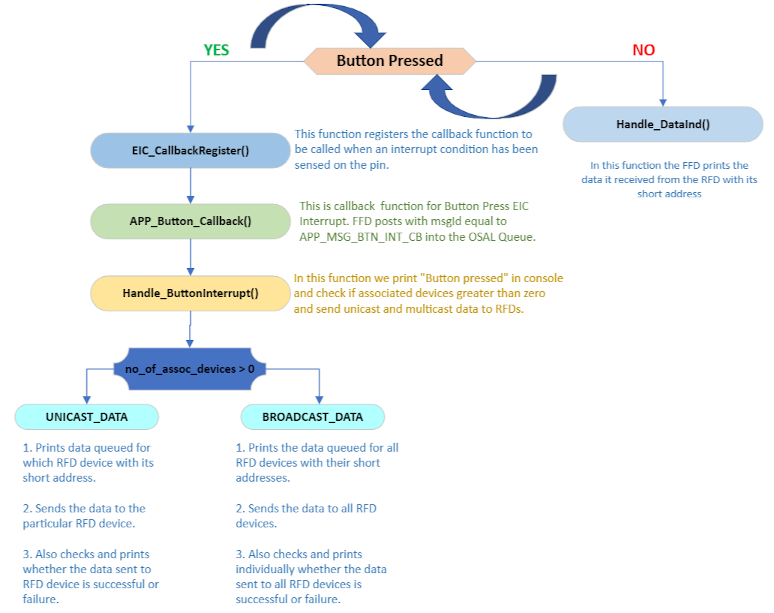
Pull messagein application context refers to a message that is held in a queue on the coordinator's side for a specific end-device. The end-device is responsible for polling the coordinator for any queued messages. If a message is queued, the coordinator will send it to the end-device. To queue data on the coordinator's side, the user button in curiosity board is used. Pressing the button will queue the data to the first associated device, followed by subsequent presses that will queue data to the second, third, and fourth devices. The fifth button press will queue data to all devices simultaneously. Pressing the button again will initiate this cycle once more.
Commissioning :
Commissioning refers to the process of connecting devices to the network created by the coordinator. Once the coordinator is powered on, it establishes a network and becomes available for end-devices to join. To add end-devices to the network, simply power them on one by one and they will automatically connect to the network.
LED indications :
In the coordinator if the blue LED in RGB LED glows the coordinator on powered on and ready.
In the RFD the following are the different led combinations indicating the following activity:
- If the blue led is constantly ON and Red led BLINKS in RGB LED - it means the RFD is not commissioned. This situation also arises if a commissioned RFD is powered off and powered on again.
- If quick green flash of the RGB LED indicates the reception of a queued data from the coordinator.
- A quick blue flash of User-LED indicates a push data was sent from RFD to the coordinator.
Limitations :
In the event of a reset or power cycle of any of the nodes, whether FFD or RFD, all network information will be lost. To re-establish the network, it is necessary to follow the commissioning procedure outlined in the commissioning section.
The following flow chart illustrates the functionality of the Co-ordinator in the Push Pull Star application.

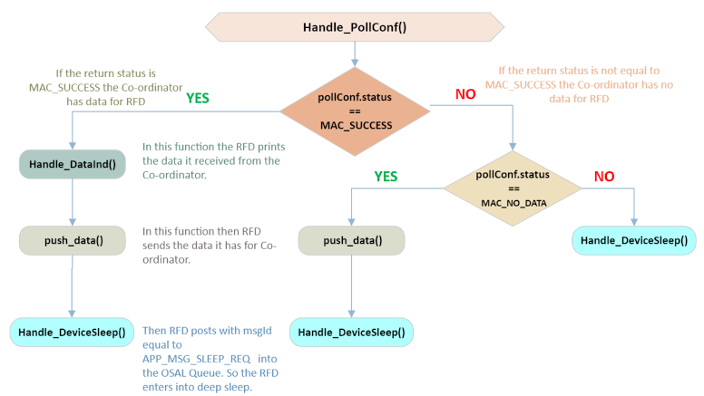
The following flow chart illustrates the functionality of the End-device in Push Pull Star application.

