The Secure project development
requires creating an Arm TrustZone-enabled MPLAB Harmony v3 project by configuring
the peripherals and memory regions in a secure mode. For the Secure project
development, use any one of the following methods:
Note: When a
SAM L11 TrustZone device is selected for creating the project, the MCC
creates and enables configuring both the Secure and Non-Secure
applications in the same project. The Secure application developer
should only follow instructions relevant to the Secure
application.
Use the SAM L11 TrustZone
Getting Started Application demonstration, which is available for download
at saml11_trustzone_getting started .
Go to the SAM L11 TrustZone Getting
Started Secure application project path:
<Demo Developed or Extracted
                        Path>\saml11_trustzone_getting_started\firmware
.
Figure 2-1. Open Existing Project
Note: In the current
implementation, when an MPLAB Harmony v3 TruztZone project is created, MPLAB X
IDE creates two projects: one for the Secure application (MPLAB X IDE project
name ending with _Secure) and the other for the Non-Secure
application.
In MPLAB X IDE Open Projects
window, select the firmware project group and then click Open
Project.
Open both the Secure and Non-secure projects by double-clicking on each project
within the project group.Figure 2-2. Add the Secure and Non
secure Projects
Click on the Projects tab.
Right-click on the Secure project name,
trustzone_sam_l11_xpro_Secure, and then select Set as Main
Project.Figure 2-3. Set the Secure Project as
the Main Project
In MPLAB X IDE, go to Tools >
Embedded and then launch MPLAB Code Configurator v5 (MCC).
Under Project Graph, select
System.
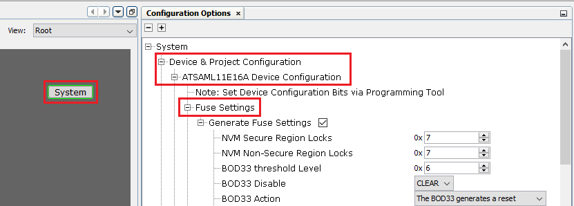
In the Configuration Options
right pane, click and expand System > Device & Project Configuration >
ATSAML11E164 Device Configuration > Fuse Settings. Figure 2-4. Expanding Configuration option
Select Generate Fuse Settings
and configure the Chip Erase Key 1 bits 31:0 through Chip Erase Key 2 bits 127:96
with unique keys as shown in the following figure. Figure 2-5. Configure the Chip Erase
Secure Key 1 and 2 in the MCC
Note: Developer A must keep
these keys confidential, which can be reused whenever an update is required for
the Secure firmware or application. In this way, Developer B or an outsider
cannot modify or erase the Secure firmware intentionally or accidentally. For
example, the Chip Erase Secure and Chip Erase All memory keys used are as
follows: 0x22222222,0x22222222,0x22222222,0x22222222. The
modified key will be stored in the Secure project configuration
file.
Click Generate to generate the
updated Chip Erase keys. Figure 2-6. Generate CodeThe following figure shows the updated pragmas for the Boot ROM Chip Erase
Secure and Chip Erase All memory regions in the initialization.c
file.Figure 2-7. Updated Boot ROM Chip
Erase Keys for Secure and All Memory Regions
Connect the SAM L11 Xplained Pro
device and program the Secure application to the device by clicking Make and
Program. Now the device is programmed with the Chip Erase keys which are
known as Secure Developer A.
Note:
When Secure application developer wants to update the Secure firmware, the Chip
Erase key must be entered under the device programming configuration options in
MPLAB X IDE before programming the Secure application.
In the MPLAB X IDE Project
Properties window, under Categories, select EDBG.
In the Options for
EDBG right pane:
For Option categories
choose Program Options.
For Erase key with
validation enter 0x22222222,0x22222222,0x22222222,0x22222222.
For Chip erase type,
choose All Non-Secure Memory Regions excluding BOOT region
(ChipErasase_S).
Note: Otherwise, the
programming will fail due to a mismatch in the Erase key. An
Erase key is 4x32 bit numbers separated by a comma. This should
match with the key entered in the MCC project graph device Fuse
Settings. The following figure shows the required steps to enter
the Erase key while programming.
Figure 2-8. Secure Project EDBG Program Options Properties
Click OK.
Set the SAM L11 device to Debug
Access Level (DAL) to DAL1. DAL1 limits the device access to the Non-Secure memory
regions and the Secure memory regions accesses are forbidden.
To set the Debug Access Level to
DAL1, follow these steps:
In the Projects
window, click and expand trustzone_sam_l11_xpro_Secure > Device
Actions, and then double-click Set DAL1.
After the Debug Access Level is set, a pop-up message will be displayed
indicating “DAL is now 1”.
Click OK.Figure 2-9. Set the Device to
DAL1 to Lock the Access to the Secure Memory Region
Note: Setting the Chip
Erase keys prevents Developer B to erase Secure memory content, but they
still can read Secure memories and then read the Chip Erase keys. To
avoid this, Developer A must set the device to DAL1 to lock Secure
memories at a debug level point. Refer to the product data sheet and
“SAM L11 Security Reference Guide” for additional
information.
Developer A shares the programmed
(Secure firmware) device with Developer B. Also, Developer A shares the SG library
and nonsecure_entry.h file with Developer B. The following figure
shows the SG library and nonsecure_entry.h file locations.Figure 2-10. SG Library and the
nonsecure_entry.h Header File
The online versions of the documents are provided as a courtesy. Verify all content and data in the device’s PDF documentation found on the device product page.