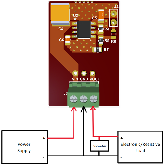
1.1.1 Sub-Modules Power-up Procedure
The following procedure applies for all BBS's. To power up each board, complete the following steps:
- Connect the power supply to the input terminals of the BBS sub-module (see BBS2: MAQ5283 High Input Voltage LDO Test Setup Example).
- Connect the load to the VOUT and GND terminals; connect the (+) side of the load to the VOUT terminal and the (-) side of the load to the GND terminal of the board (see BBS2: MAQ5283 High Input Voltage LDO Test Setup Example). The maximum load varies with the input and output voltage (refer to the Data Sheet for more information on the typical operating ratings). By default, the EN pin is pulled high through a resistor.
- When the power supply is turned on, a voltmeter can be used to monitor VOUT. The measured output voltage should be very close to the nominal value. Adjusting the input voltage and load should not cause the output to vary more than a few percentage points, depending on each LDOs output voltage accuracy.