The clock
output can be used to feed the target device with a more accurate clock if this is
needed for the application. By default, this clock is disconnected from the target by a
not mounted resistor.
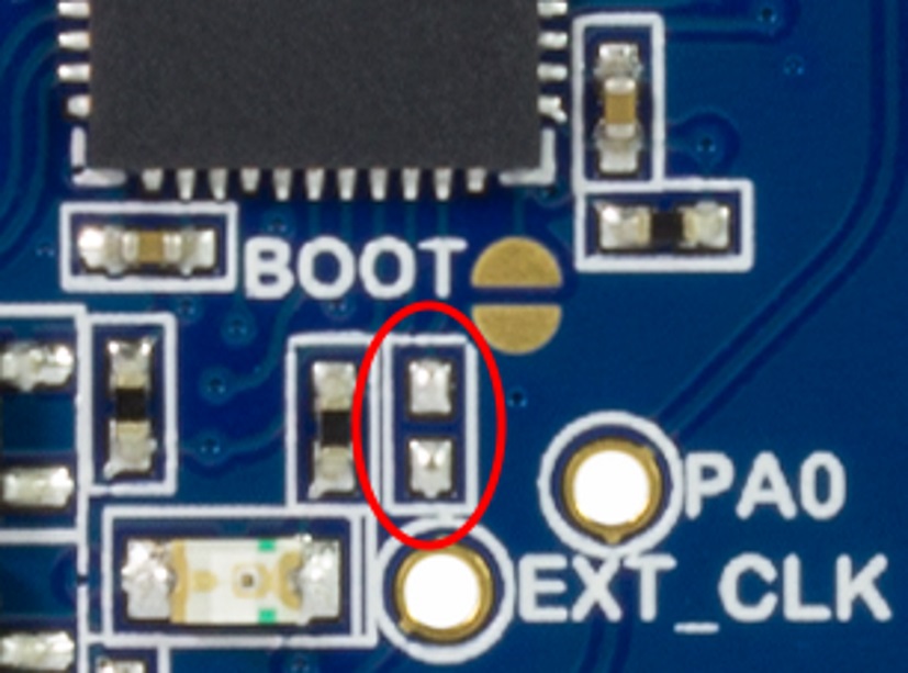
To connect the external clock to the ATtiny817, a 0Ω resistor or strap has to be soldered in
the footprint, as shown in the figure below (R205). Figure 3-1. External Clock
Footprint
The mEDBG CPU clock frequency depends on the selected voltage, see the table
below.
Table 3-2. CPU Clock vs. Voltage
Target Voltage
mEDBG CPU Clock
3.3V
8 MHz
5.0V
16 MHz
The online versions of the documents are provided as a courtesy. Verify all content and data in the device’s PDF documentation found on the device product page.