
3.1.3 Secure CAN Bootloader with PIC32CX SG61 Curiosity Ultra Evaluation Board
Description
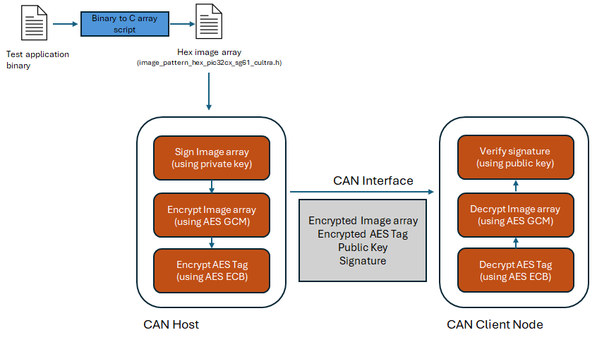
This application demonstrates usage of the internal Hardware Security Module (HSM) of the PIC32CX SG61 for securely transferring application firmware between Host and Client over a CAN bus.
The package contains two projects:
- pic32cx_sg61_secure_can_host:
Signs and encrypts a test application firmware. The encrypted firmware and is sent over CAN interface to the client node
- pic32cx_sg61_secure_can_node_bootloader:
Receives the encrypted application firmware on a temporary RAM buffer, decrypts and verifies the signature. Up on successfull verification, the firmware is programmed to the device flash.
A device reset is triggered automatically, and the received test application starts executing after the reset.
Loading Test Application Firmware
The pic32cx_sg61_secure_can_host project in this release already has a LED blinking test application Hex array included in the path -> /firmware/pic32cx_sg61_secure_can_host/firmware/src/image_pattern_hex_pic32cx_sg61_cultra.h.
To use any application other than this:
- Generate binary file for the application referring to Application Configurations.
- Convert binary to a C style array containing Hex output. The Binary to C Array script can be used to perform this. The output Hex header file from this can be included directly to the secure_can_host project and compiled.
Flow Chart
Modules/Technology Used
- Peripheral Modules
- SERCOM (USART)
- SERCOM (SPI)
- NVMCTRL
Hardware Used
Software/Tools Used
This project has been verified to work with the following versions of software tools:
Refer Project Manifest present in harmony-manifest-success.yml under the project folder firmware/src/config/default.
- Refer the Release Notes to know the MPLAB X IDE and MCC Plugin version.
- Any Serial Terminal application like Tera Term terminal application.
Because Microchip regularly updates tools, occasionally issue(s) could be discovered while using the newer versions of the tools. If the project does not seem to work and version incompatibility is suspected. It is recommended to double-check and use the same versions that the project was tested with. To download original version of MPLAB Harmony v3 packages, refer to document How to Use the MPLAB Harmony v3 Project Manifest Feature (DS90003305).
Hardware Setup
- PIC32CX SG61 Curiosity Ultra Evaluation is used for both Host Development
kit and Client Node Development kit.
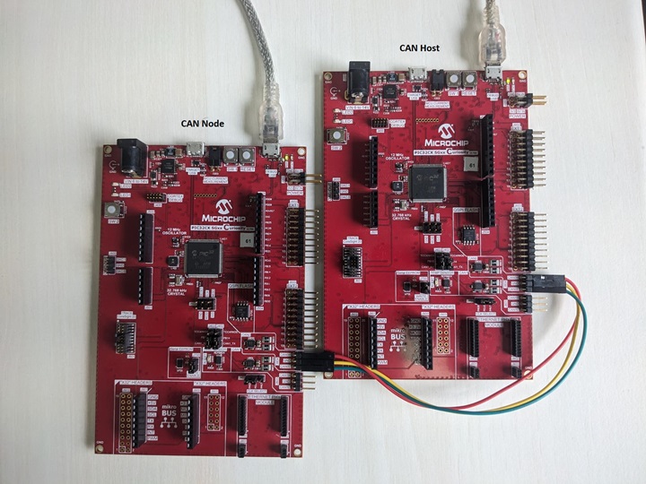
- Connect PIC32CX SG61 Curiosity Ultra
Evaluation board to another PIC32CX SG61 Curiosity Ultra Evaluation board as per the
pin connections shown below:
PIC32CX SG61 Curiosity Ultra Evaluation board - 1 PIC32CX SG61 Curiosity Ultra Evaluation board - 2 CANH, CAN0 CANH, CAN0 CANL, CAN0 CANL, CAN0 GND, CAN0 GND, CAN0 - Connect the Debug USB port on the evaluation boards to the computer using a micro USB cable.
Running the Demo
- Open a Terminal application, for
example Tera Term, on the computer and configure the serial port settings for
Host Development kit as follows:
- Baud : 115200
- Data : 8 Bits
- Parity : None
- Stop : 1 Bit
- Flow Control : None
Open another instance of the terminal and configure it with the same settings as above, for the Client Node Development kit.
- Open the host application project \pic32cx_sg61_secure_can_host\firmware\pic32cx_sg61_secure_can_host.X in the IDE.
- Build and program the firmware using
the IDE on to the Host development kit.
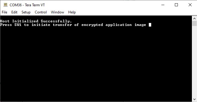
- The user should see the following
output in the console corresponding to the Host Development kit.
- The user should see the following
output in the console corresponding to the Host Development kit.
- Open the bootloader project pic32cx_sg61_secure_bootloader\firmware\pic32cx_sg61_secure_can_node_bootloader\firmware\pic32cx_sg61_secure_can_node_bootloader.X in the IDE.
- Build and program the application
using the IDE on to the Client Node development kit.
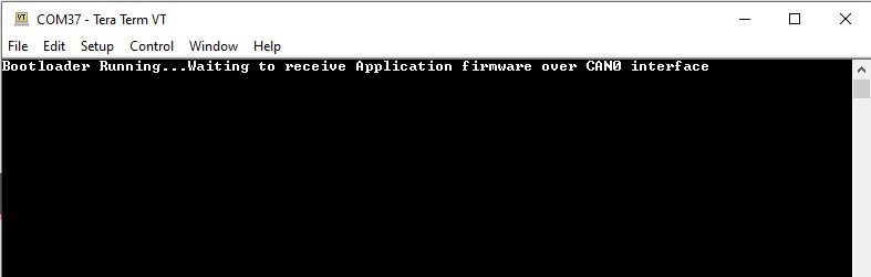
- LED1 will be turned-on to indicate that bootloader code is running on the target.
- The user should also be able to
see the following output in the console corresponding to the Client Node
development kit.
- Press the Switch SW1 on the Host development kit to trigger programming of the application binary.
- Once the programming is completed,
- LED1 on the Host development kit will be turned on indicating success.
- The Client Node development kit will be automatically reset. Upon re-start, the boot-loader will jump to the user application.
- If the test application is programmed then LED1 should start blinking.
- The below output can be seen on
the respective consoles of the Host and Client development kit.
Figure 3-2. Host Node 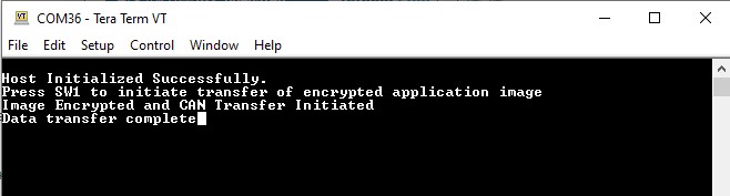
Figure 3-3. Client Node 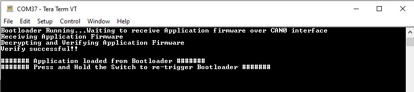
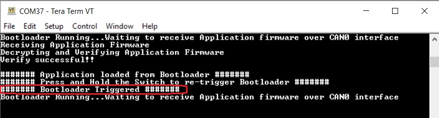
- Press and hold the Switch SW1
to trigger Bootloader from test application and the user should see below output.
- Press Reset button on the Host development kit followed by SW1 to reprogram the application binary.
Comments
- This application demo builds and
works out of box by following the instructions above in Running the Demo
section. If the user needs to enhance/customize this application demo, should use the
MPLAB Harmony v3 Software framework. Refer links below to setup and build the
applications using MPLAB Harmony.
- How to Setup MPLAB Harmony v3 Software Development Framework (DS90003232).
- How to Build an Application by Adding a New PLIB, Driver, or Middleware to an Existing MPLAB Harmony v3 Project (DS90003253).
- MPLAB Harmony v3 is also configurable through MPLAB Code Configurator (MCC). Refer to the below links for specific instructions to use MPLAB Harmony v3 with MCC.