20 SRPORT – Signal Routing Port
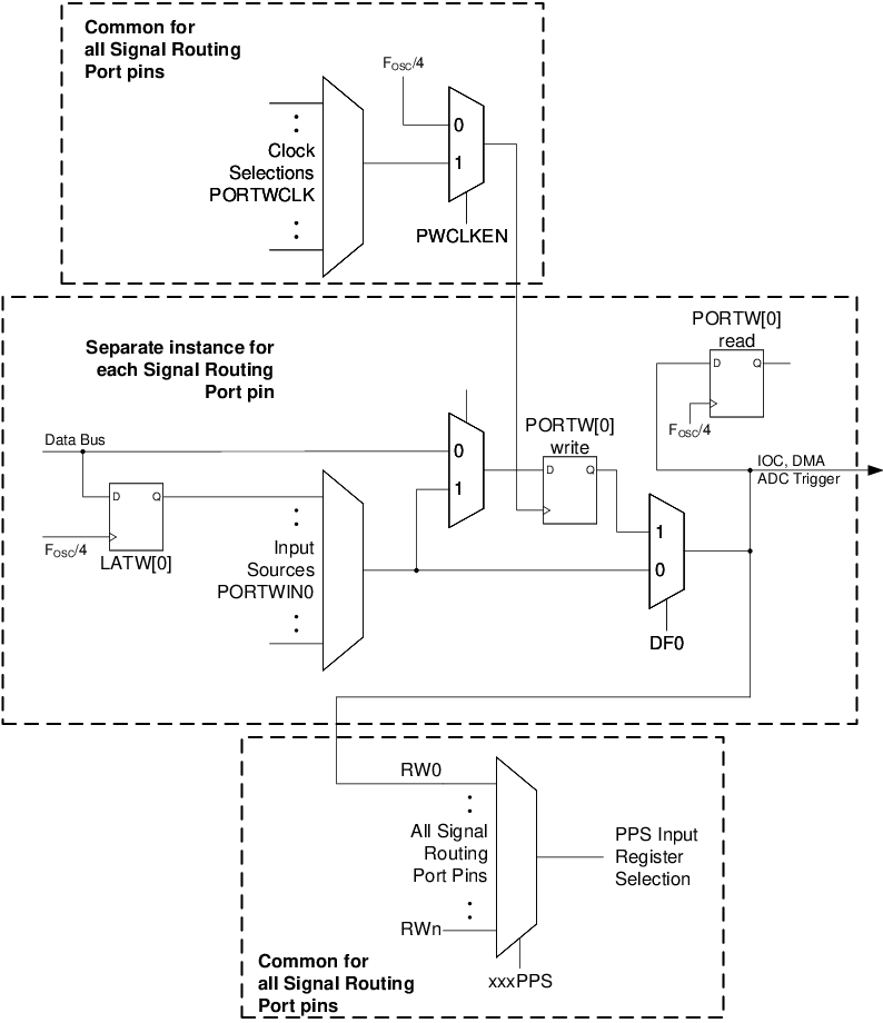
The Signal Routing Port module allows for interconnection of multiple peripherals internal to a device without the need for an external I/O pin. A device may contain multiple Signal Routing Ports, each Signal Routing Port consisting of eight pins that are represented by eight bits similar to regular device ports.
This module can be used as a high-level input selection multiplexer for the entire device, which can connect the output of digital peripherals into the inputs of other peripherals internally without using any external I/O pins. Using the Signal Routing Port to connect peripherals in this manner allows the user to connect multiple core independent peripherals on the device to form hardware-based state machines.
In addition to the input selection multiplexers, this module also offers a flip-flop for each Signal Routing pin to latch the output value. The flip-flop may be bypassed to connect the output of one peripheral directly to the input of another. Figure 20-1 shows the block diagram of a typical Signal Routing Port.
- 8 Signal Routing pins for each Signal Routing Port
- Software read/write through PORTW and LATW registers
- Extensive clock selection and input source selection
- Individual flip-flop for each bit to latch output value
- Common clock source for all bits of a Signal Routing Port
- Individual input control for each bit of Signal Routing Port
- Individual output available to other modules via PPS input
- Interrupt-on-Change, DMA and ADC triggers for each Signal Routing pin
- There is one Signal Routing Port available on this device – PORTW.

