3 DT100104 Rev 4 Errata
Revision #4 of the DT100104 was produced with the ECC608-TMNGTLS device in position U8 instead of position U5 as labeled on the silk screen of the board. An ATECC608C-MAHDA (TrustCUSTOM) is in position U5 instead of position U8. The board is fully functional and was tested but was manufactured with this anomaly.
Identifying the Board
| Method # | Method to Identify | Image |
|---|---|---|
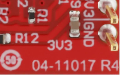
| 1 | On the backside of the board, in the lower right corner, is the board revision number as shown in the figure to the right. The R4 indicates that this is revision 4 of the board. |
 |
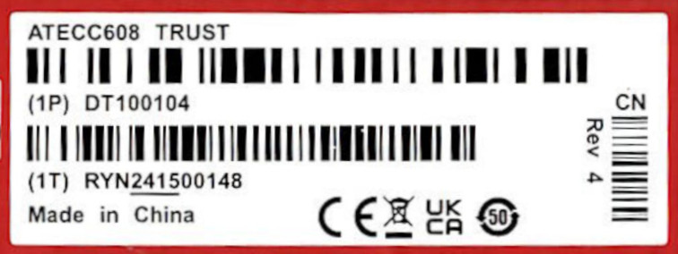
| 2 | The box that the board is packaged in will show revision #4 on the right side of the label on the side of the box. |
 |
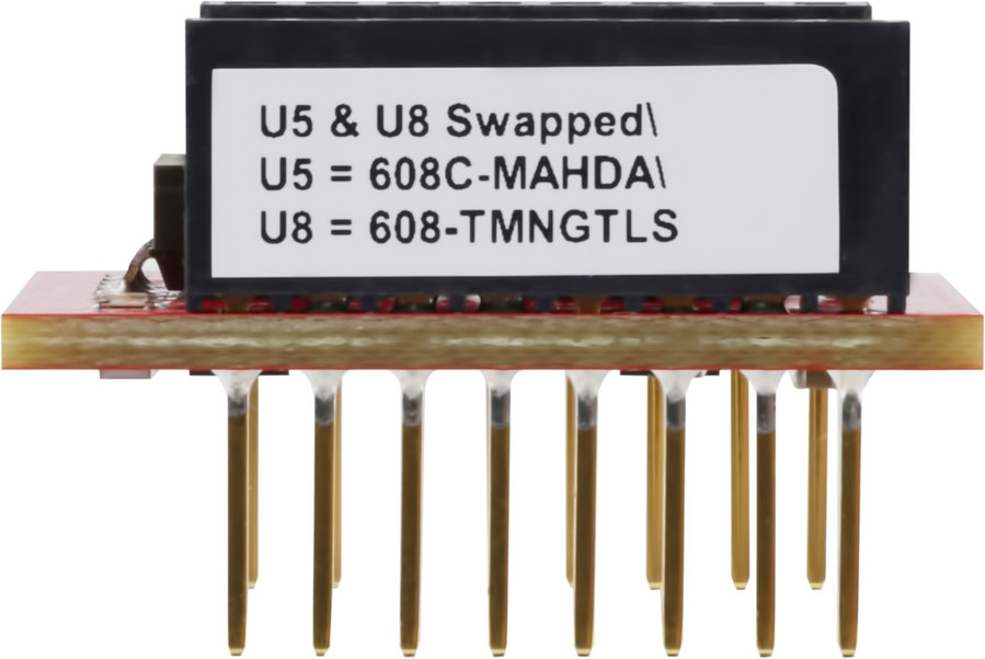
| 3 | A special label on the side of the mikroBUS™ connector was added for convenience and indicates that devices U5 and U8 were swapped and which device is in which position. |
 |
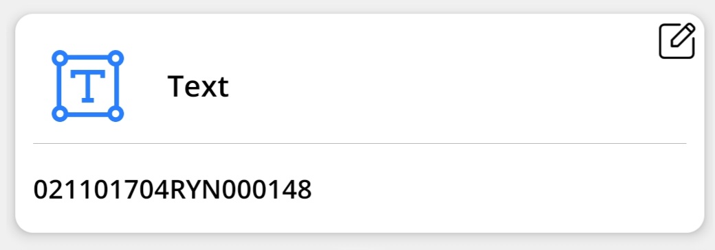
| 4 | Scanning the barcode that is on the backside of the DT100104 board, as shown in image Figure , will display the text shown to the right. The characters ‘04’ before the ‘RYN’ identify the board as a revision #4 board. Note that the last six digits are the actual serial number of the board and will be unique for each board. |
 Note: Image will vary based on the barcode
scanner used.
|
Affected Board Revisions
Only revision #4 of the DT100104 board has the U5 and U8 devices swapped.
| PCB Label(1, 3) | Box Label(2, 3) | |
|---|---|---|
| Min Serial # | 021101704RYN000001 | RYN241500001 |
| Max Serial # | 021101704RYN000200 | RYN241500200 |
- See the image in Method #4 in Identifying the Board.
- See the image in Method #2 in Identifying the Board.
- The last six digits of the PCB serial # and the Box Serial # may or may not correspond. This is not a cause for concern.
Work Around
| Switch # | DIP Switch | Device U# | Secure Element | Trust Element Type |
|---|---|---|---|---|
| SW1 | 1 | U1 | ATECC608C-TNGTLS | Trust&GO |
| 2, 3, 4 | U2, U3, U4 | ATECC608C-TFLXTLS | TrustFLEX | |
| SW2 | 5, 6, 7 | U5, U6, U7 | ATECC608C-MAHDA | TrustCUSTOM |
| 8 | U8 | ECC608-TMNGTLS | Trust Manager |
Planned Corrections
Revision #5 of the DT100104 board is planned to correct the issue described in this section. With this revision, the board will operate as described in this user manual. Production of the revision #5 board will be determined by the depletion of the inventory of revision #4. The revision #5 version of the board will show revision 04-11017-R5 on the backside of the board. In addition, Methods #2 and #4, as described in Identifying the Board, will also be valid.
