
1.1.4 PIC32CXMTSH-DB Evaluation Kit: Building and Running the UART Bootloader applications
Downloading and building the application
To clone or download this application from Github,go to the main page of this repository and then click Clone button to clone this repo or download as zip file. This content can also be download using content manager by following these instructions
Path of the application within the repository is apps/uart_bootloader/
To build the application, refer to the following table and open the project using its IDE.
Bootloader Application
| Project Name | Description |
|---|---|
| bootloader/firmware/pic32cx_mtsh_db.X | MPLABX Project for PIC32CXMTSH-DB Evaluation Kit |
Test Application
| Project Name | Description |
|---|---|
| test_app/firmware/pic32cx_mtsh_db.X | MPLABX Project for PIC32CXMTSH-DB Evaluation Kit |
Setting up PIC32CXMTSH-DB Evaluation Kit
- Connect a mico-USB cable from USB UART to Computer
- Power on the board using a 12V power supply on J3
- Attach a debugger to the SWD/JTAG port J17
Setting up the host script
- Refer to Bootloader Host Script Help for setting up the btl_host.py utility used to send the application binary from host PC
Running the Application
Open the test application project test_app/firmware/pic32cx_mtsh_db.X in the IDE
Build the project to generate the binary (Do not program the binary)
Open the bootloader project bootloader/firmware/pic32cx_mtsh_db.X in the IDE
Build and program the application using the IDE
Run the btl_host.py from command prompt to program the application binary
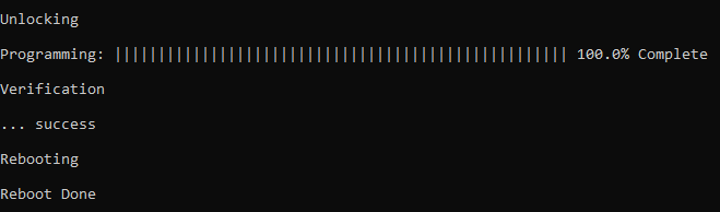
python <harmony3_path>/bootloader/tools/btl_host.py -v -i <COM PORT> -d pic32cx_mt -a 0x1002000 -f <harmony3_path>\bootloader_apps_uart\apps\uart_bootloader\test_app\firmware\pic32cx_mtsh_db.X\dist\pic32cx_mtsh_db\production\pic32cx_mtsh_db.X.production.binFollowing snapshot shows output of successfully programming the test application
- Rebooting and Reboot Done messages in below output signifies that bootloading is successful
If the above step is successful, press the RESET button. The LED_RED should then begin blinking.
Open the Terminal application (Ex.:Tera Term) on the computer
Configure the serial port settings as follows:
Baud : 115200
Data : 8 Bits
Parity : None
Stop : 1 Bit
Flow Control : None
Reset or Power cycle the device
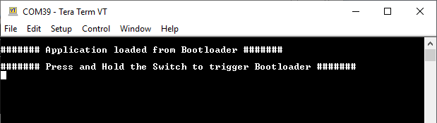
LED_RED should start blinking and you should see below output on the console
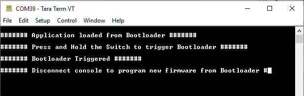
Press and hold the Switch SCROLL_DOWN to trigger Bootloader from test application and you should see below output
Repeat Steps 5-11 once and jump to Step-14.
- This step is to verify that bootloader is running after triggering bootloader from test application in Step 12
Press and hold the Switch SCROLL_DOWN and then press Reset button or Power cycle the device to force trigger bootloader at startup
Repeat Steps 5-11 once
- This step is to verify whether bootloader is triggered by switch press at reset
Additional Steps (Optional)
- To bootload any other application refer to Configuring an application to be bootloaded for CORTEX-M based MCUs
Parent topic:UART Bootloader