
1.2.2 PIC32CZ-CA80 Curiosity Ultra Board: Building and Running the UART Fail Safe Bootloader Applications
Downloading and Building the Application
To clone or download this application from Github, go to the main page of this repository and then click Clone button to clone this repo or download as zip file. This content can also be download using content manager by following these instructions.
Path of the application within the repository is apps/uart_fail_safe_bootloader/.
To build the application, refer to the following table and open the project using its IDE.
Bootloader Application
| Project Name | Description |
|---|---|
| bootloader/firmware/pic32cz_ca80_curiosity_ultra.X | MPLABX Project for PIC32CZ-CA80 Curiosity Ultra board |
Test Application
| Project Name | Description |
|---|---|
| test_app/firmware/pic32cz_ca80_curiosity_ultra.X | MPLABX Project for PIC32CZ-CA80 Curiosity Ultra board |
Setting Up PIC32CZ-CA80 Curiosity Ultra Board
- Connect the Debug USB port on the board to the computer using a micro USB cable
Setting Up the Host Script
Refer to the Bootloader Host Script Help for setting up the btl_host.py utility used to send the application binary from host PC
Refer to the Bootloader App Merge Bin Help for setting up the btl_app_merge_bin.py utility used to merge the bootloader binary and application binary
Running the Application
Open the test application project test_app/firmware/pic32cz_ca80_curiosity_ultra.X in the IDE.
Build the project to generate the binary (Do not program the binary).
Open the bootloader project bootloader/firmware/pic32cz_ca80_curiosity_ultra.X in the IDE.
Build and program the application using the IDE.
Run the btl_host.py from command prompt to program the application binary.
The application is programmed into Bank B
python <harmony3_path>/bootloader/tools/btl_host.py -v -s -i -d pic32cz -a 0xc400000 -f <harmony3_path>\bootloader_apps_uart\apps\uart_fail_safe_bootloader\test_app\firmware\pic32cz_ca80_curiosity_ultra.X\dist\default\production\pic32cz_ca80_curiosity_ultra.X.production.bin
Following figure shows output of successfully programming the test application.
- Swapping Bank And Rebooting and Reboot Done messages in below output signifies that bootloading is successful
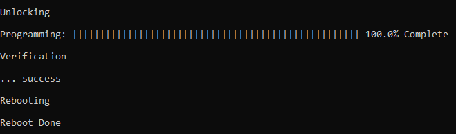
If above step is successful then the LED0 should start blinking.
Open the Terminal application (Ex.:Tera Term) on the computer.
Configure the serial port settings as follows:
- Baud: 115200
- Data: 8 Bits
- Parity: None
- Stop: 1 Bit
- Flow Control: None
Reset or Power cycle the device.
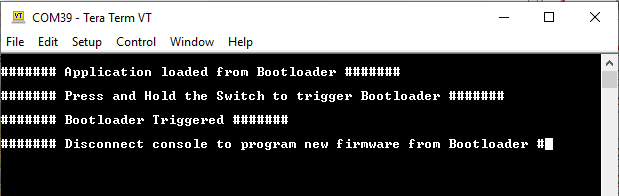
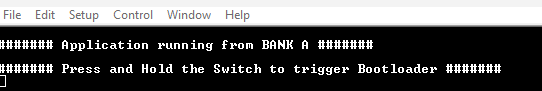
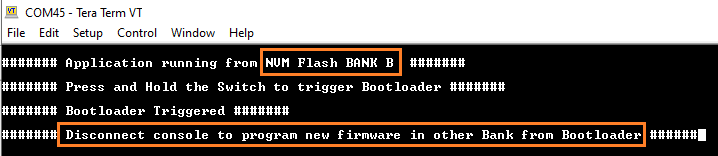
LED1 should start blinking and the user should see below output on the console.
- The Program Flash Bank Can be BANK A or BANK B based on from where the program is running
Press and hold the Switch SW0 to trigger Bootloader from test application to program firmware in other bank and the user should see below output.
Disconnect UART console.
Re-run Step 5 to program the application into the opposite bank after triggering the bootloader with SW0.
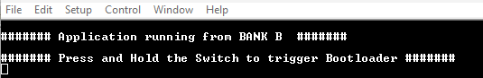
- The console output should confirm that the new application was programmed successfully.
Repeat Steps 5-14 once.
- This step is to verify that bootloader is running after triggering bootloader from test application in Step 12
- Also to program the new firmware in opposite bank
- The user should see other Bank in console displayed compared to first run
- Revert the changes done in Step 5
- Regenerate the project
- Start from Step 4
- To bootload any other application refer to the Configuring an application to be bootloaded for CORTEX-M based MCUs
Note:
If demo needs to be restarted from beginning:
Additional Steps (Optional)