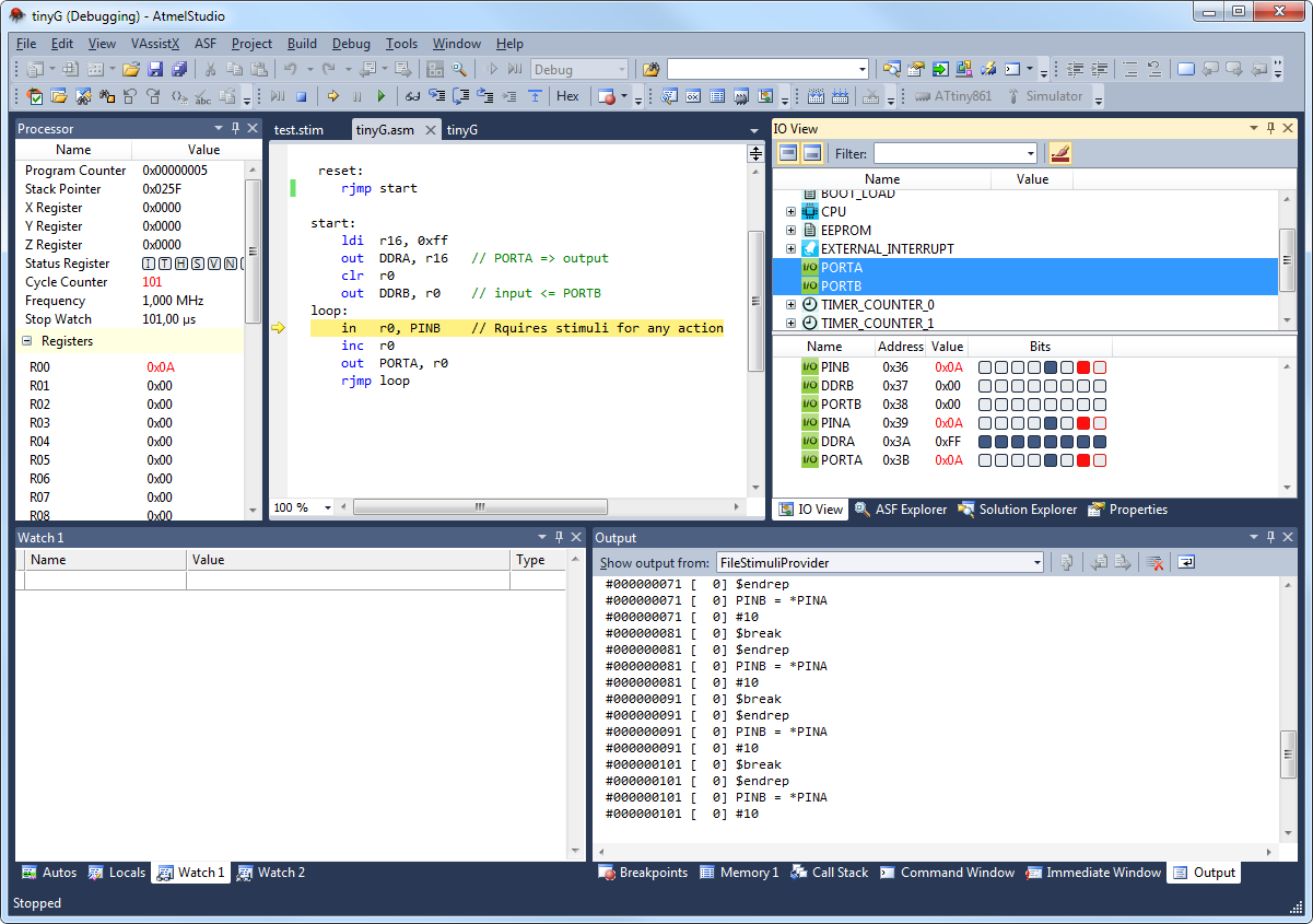
1.2.2.5 Example Stimuli Session
Session 1; Simple AVR® Program
The following example should work with any ATtiny or ATmega device having at least two GPIO
ports (PORTA and PORTB). It should be run with the I/O
view active and set up to show the PORTA and PORTB
modules.
This program sets up
PORTA as output and
PORTB as input, and then loops, reading whatever is present on
PINB, increments it by one, and outputs it at
PORTA.
reset:
	rjmp start
start:
	ldi  r16, 0xff
	out  DDRA, r16   // PORTA => output
	clr  r0
	out  DDRB, r0    // input <= PORTB
loop:
	in   r0, PINB    // Requires stimuli for any action
	inc  r0
	out  PORTA, r0
	rjmp loop
Without stimuli, this program will read
0 from PINB, and output 1 to
PORTA, forever.Now apply the following stimuli file:
// Example stimuli file, feeds any output on PINA back to PINB.
#10
$repeat 10
	PINB = *PINA
	#10
	$break
$endrep
PINB will now be driven by the output from PORTA every
10th cycle, and the effect will be directly visible in the I/O view.
Thanks to the $break directive inside the loop, the program will stop
every 10 cycles without any breakpoint in the program.
Session 2; Simple AVR® Logging
The following example is made for ATmega328P but should work with most ATtiny or ATmega
devices. This program starts
TIMER0 and then enters a loop, constantly
adding 1 to the value in PIND and assigning the result to
PORTD.
#include <avr/io.h>

int main(void)
{
	DDRD = 0xFF;
	TCCR0B = (1<<CS00);
    while(1)
    {
        PORTD = PIND + 1;
    }
}
When applying the following stimuli, it will create a log file that starts logging the value of
PORTD and PIND. After 20 cycles, it changes to
logging PIND and TCNT0, and after another 20 cycles,
it continues to only log PIND for 60 cycles.
$log PORTD
$log PIND
$startlog mega328p_log_output.stim
#20
$unlog PORTD
$log TCNT0
#20
$unlog TCNT0
#60
$stoplog
$break
This will produce a file called
mega328p_log_output.stim
with the following
content:#6
PORTD = 0x01
#1
PIND = 0x01
#4
PORTD = 0x02
#1
PIND = 0x02
#4
PORTD = 0x03
#1
PIND = 0x03
#3
TCNT0 = 0x10
TCNT0 = 0x11
#1
TCNT0 = 0x12
#1
PIND = 0x04
TCNT0 = 0x13
#1
TCNT0 = 0x14
#1
TCNT0 = 0x15
#1
TCNT0 = 0x16
#1
TCNT0 = 0x17
#1
PIND = 0x05
TCNT0 = 0x18
#1
...Session 3; Logging PWM Ouput
The following example is made for ATmega328P but should work with most ATtiny or ATmega
devices. This program starts
TIMER0 in fast PWM mode. The output of the
PWM signal on PD6 is controlled by PB0. 1 on PB0 enables PWM output, 0 on PB0
disables it.
#include <avr/io.h>

int main(void)
{
	DDRB = 0x00;
	DDRD = 0xFF;
	PORTD = 0x00;
	OCR0A = 0x20;
	TCCR0A = (1<<COM0A0 | 1<<WGM01 | 1<<WGM00);
	TCCR0B |= (1<<CS00);
    while(1)
    {
		if(PINB & 0x01)
			TCCR0B |= (1<<WGM02);
		else
			TCCR0B &= ~(1<<WGM02);
    }
}
When applying the following stimuli, it will create a log file that starts logging the value of
PINB and PIND. After 20 cycles, it also starts to
log TCNT0. Five cycles later, it applies a 1 to PB0 to start the PWM
output, and another five cycles later, it turns off logging of TCNT0. For the next 200
cycles, the PWM output on PD6 will be logged before it is turned off by setting PB0 to
0. Then it continues for another 200 cycles before it breaks.
$log PINB
$log PIND
$startlog mega328p_log_output.stim
#20
// Log TIMER0 counter
$log TCNT0
#5
// Set pin PB0 to '1', Start PWM output
PINB |= 0x01
#5
// Stop logging TIMER0 counter
$unlog TCNT0
#200
// Set pin PB0 to '0', Stop PWM output
PINB &= 0xFE
#200
$stoplog
$break
This will produce a file called
mega328p_log_output.stim
with the following
content:#20 TCNT0 = 0x09 TCNT0 = 0x0a #1 TCNT0 = 0x0b #1 TCNT0 = 0x0c #1 TCNT0 = 0x0d #1 TCNT0 = 0x0e #1 TCNT0 = 0x0f #1 PINB = 0x01 TCNT0 = 0x10 #1 TCNT0 = 0x11 #1 TCNT0 = 0x12 #1 TCNT0 = 0x13 #15 PIND = 0x40 #33 PIND = 0x00 #33 PIND = 0x40 #33 PIND = 0x00 #33 PIND = 0x40 #33 PIND = 0x00 #22 PINB = 0x00 #11 PIND = 0x40 #1 PIND = 0x00
