
5.3.2 AC Parameters: I2C Interface
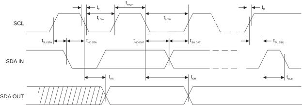
| Parameter | Sym. | Min. | Max. | Units |
|---|---|---|---|---|
| SCL Clock Frequency | fSCL | 0 | 400 | kHz |
| SCL High Time | tHIGH | 600 | — | ns |
| SCL Low Time | tLOW | 1200 | — | ns |
| Start Setup Time | tSU.STA | 600 | — | ns |
| Start Hold Time | tHD.STA | 600 | — | ns |
| Stop Setup Time | tSU.STO | 600 | — | ns |
| Data In Setup Time | tSU.DAT | 100 | — | ns |
| Data In Hold Time | tHD.DAT | 0 | — | ns |
| Input Rise Time(1) | tR | — | 300 | ns |
| Input Fall Time(1) | tF | — | 300 | ns |
| Clock Low to Data Out Valid | tAA | 50 | 900 | ns |
| Data Out Hold Time | tDH | 50 | — | ns |
| Time Bus Must be Free before a New Transmission Can Start(1) | tBUF | 1200 | — | ns |
| Glitch Filter(3) | tIGNORE_I2C | 50 | 250 | ns |
Note:
- Host system must ensure this timing is met.
- AC measurement conditions:
- RL (connects between SDA and VCC): 1.2 kΩ (for VCC = +1.65V to +5.5V)
- Input pulse voltages: 0.3VCC to 0.7 VCC with CMOSenable = 1
- Input rise and fall times: ≤ 50 ns
- Input and output timing reference voltage: 0.5 VCC
- The glitch filter ensures that all pulses below the min value will be suppressed but may suppress values as great as the max value over all process, voltage and temperature conditions.