
2.1 Power Sources
The following figure shows the power sources of the MCP2222.
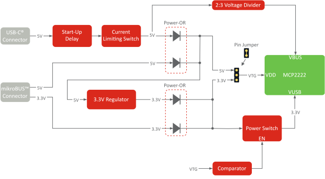
The MCP2222 Breakout Board supports three main input power sources:
Power sourced from the mikroBUS™ connector 5V pin.
A 3.3V supply derived from the 5V source using the on-board 3.3V regulator
Power sourced from the mikroBUS connector 3V3 pin.
Power sourced from the USB Type-C® connector VBUS pin (typically 5V).
A 3.3V supply derived from the 5V source using the on-board 3.3V regulator
To support multiple power sources, the board includes two diode OR gates: One for the 5V supplies and one for the 3.3V supplies. The 5V and 3.3V outputs are connected to the two ends of the voltage-select jumper.
Alternatively, a 5V or 3.3V supply can be fed directly through the VTG pin. In this case, ensure that the voltage-select jumper is not connected.