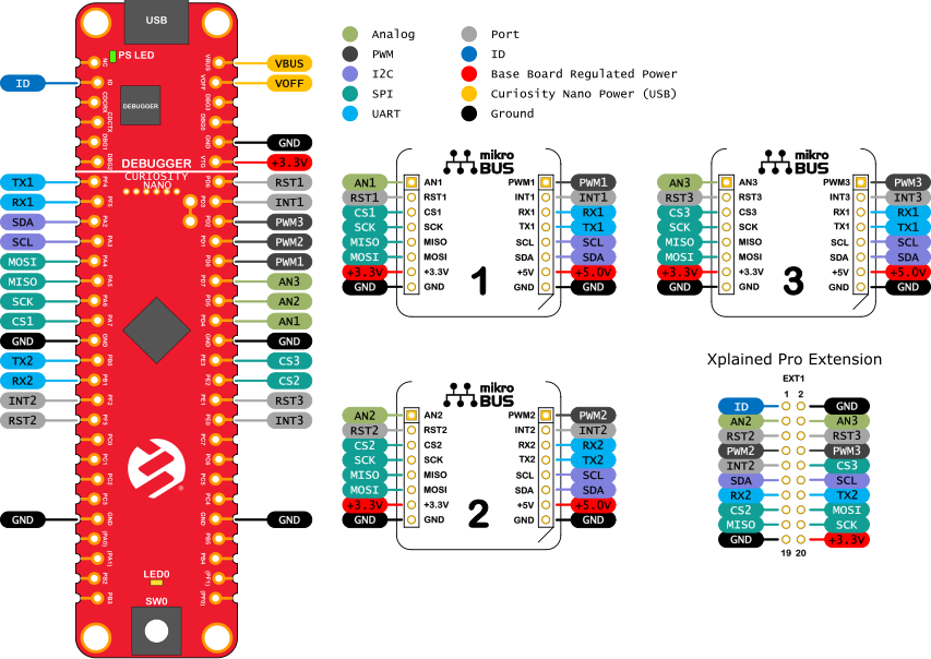
3.1 Curiosity Nano Base for Click boards™ Pinout
The figure below shows how a Curiosity Nano microcontroller board connects to each of the mikroBUS™ sockets and Xplained Pro extension.
Check the appendix of the user guide for the microcontroller board to figure out how the microcontroller I/Os are routed on the Curiosity Nano Base for Click boards™.

SPI and I2C are shared between all connected hardware. The SPI bus has three unique Chip Select signals routed to each mikroBUS™ socket.
UART1 (TX1 and RX1) is shared between mikroBUS™ sockets 1 and 3, while UART2 (TX2 and RX2) is shared between mikroBUS™ socket 2 and the Xplained Pro extension header.
The Xplained Pro extension header is shared with mikroBUS™ sockets 2 and 3. If using several add-on boards at the same time, make sure to check for any conflicting signals.
The figure above shows how to identify which microcontroller pins on an AVR128DA48 Curiosity Nano are connected to mikroBUS™ socket 1.
- Identify which pins are used on the Click board.
- Find the pin name inside the mikroBUS™ socket on the Curiosity Nano Base for Click boards™.
- Locate the same pin names next to the Curiosity Nano footprint.
- Read the pin names on the AVR128DA48 Curiosity Nano board.
SDA is connected to pin PC2, and SCL is connected to pin PC3 of the AVR128DA48.
