
2 Crosstalk
As the feature sizes have been shrinking with process-technology scaling, the spacing between adjacent interconnect wires/traces keeps decreasing in every process technology. When a signal on one of these wires generates a rising/falling edge, this can have an effect on a neighboring wire and is generally referred to as crosstalk. Crosstalk can be due to electric or magnetic field lines interacting between two adjacent lines, and is due to the capacitance and inductance between them.
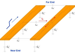
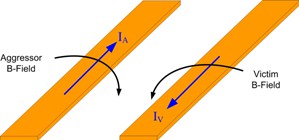
In inductive crosstalk, magnetic fields exist as the current travels down the aggressor line. These B-field lines induce B-field lines around the victim line, which, in turn, creates current traveling in the opposite direction. The direction of the induced current creates a negative voltage at the far-end and a positive voltage at the near-end as it flows through the termination impedances.
The effects of crosstalk on an oscillator are largely contributed from the PCB to which the oscillator is mounted. By following proper design guidelines, crosstalk can be minimized/eliminated. Other methods include inserting buffers, cell resizing, track reassignment of the victim traces, and allocating additional spacing to victim traces.