
10.3 Indicator Lights (LEDs)
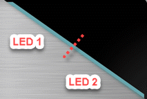
The top of MPLAB ICD 5 unit has two light pipes butted against to each other, each illuminated by an LED.
The expected start-up sequence for the debugger is:
- Purple - steady on for approximately 3 seconds.
- Blue - flashing for approximately 2 seconds while the debugger runs a power-on self-test.
- Blue - steady on. The debugger is ready.
The following table advises how to read the indicator lights.
| LED 1 | LED 2 | Description |
|---|---|---|
| Normal Modes | ||
| Blue | Blue | Power is connected; debugger in standby; Network ready to connect |
| White | Blue | Network connected |
| White, slow blink | Blue | MPLAB X IDE/MPLAB IPE has initiated communication with ICD 5 over the network |
| Red | Blue | Network connection failure/error |
| Yellow | Blue | Power target circuit from ICD 5 checked |
| Green | Blue | Power target circuit from ICD 5 unchecked |
| Green, slow blink | Blue | DGI connected |
| Purple | Purple | Bootloader is running |
| Yellow | Yellow | Debugger is busy |
| Red | Red | An operation has failed |
| Bootloader Errors | ||
| Purple | Red, slow blink | Problem accessing the debugger’s serial EEPROM |
| Purple | Red, fast blink | Bootloader API commands cannot be processed |
| White, fast blink | White, fast blink | A runtime exception occurred in the tool firmware |