1.2.3 Create Blinky LED project
This section offers a step-by-step guide to configure X2C scope in your example project.
Required Software
The instructions in this tutorial assume that you have already installed the following software:
- MPLAB X Integrated Development Environment
- MPLAB XC32/32++ C Compiler
Required Hardware
The following hardware is used to create a sample X2C Scope project. You can use these steps with different hardware platforms as well. While the overall process remains the same, some steps may vary slightly depending on the hardware.
Setting up X2C Model Project in MPLAB Harmony 3
-
Launch the MCC from MPLAB® IDE (if not already opened) as shown below.
Figure 1-1. Figure.1 - Launching MCC 
-
Add X2C Model from "Device Resources > X2C" into the Project Graph as shown below:
Figure 1-2. Figure.2 - Add X2C Model to the project graph 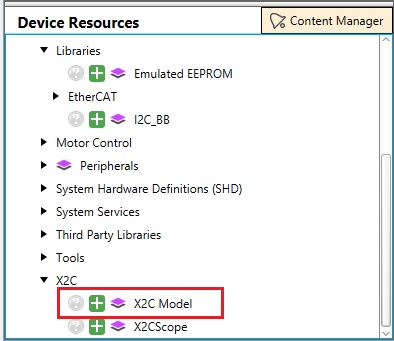
-
Configure UART instance and Scope size in X2C model as shown below:
Figure 1-3. Figure.3 - Configure X2C Model 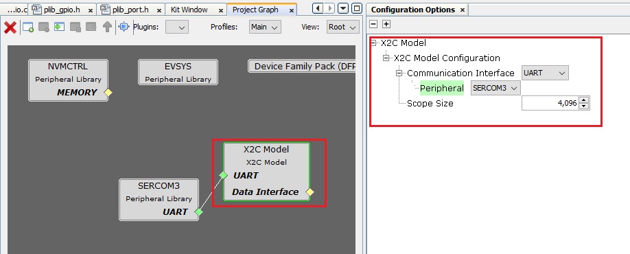
-
Configure SERCOM peripheral as shown below:
Figure 1-4. Figure.4 - Configure UART peripheral 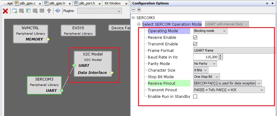
-
Add TC0 Model from "Device Resources > TC" into the Project Graph and configure as follows:
Figure 1-5. Figure.5 - Add TC0 to the project graph 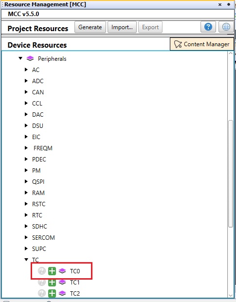
-
Configure the timer period of TC0 to match the rate of model execution (e.g., 50µS) and enable the period match interrupt:
Figure 1-6. Figure.6 - Configure TC0 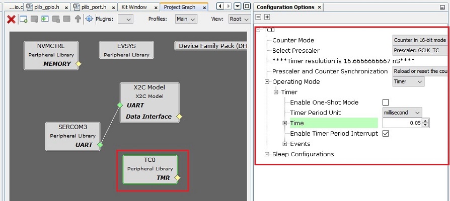
-
Navigate to "Project Graph -> Plugins -> Pin Configuration" to configure the following pins:
- Configure PD09 and PD10 as digital inputs for button switches BTN_S2 and BTN_S3:
-

- Configure PB26 and PB27 as digital outputs for LEDs D2 and D17 respectively:
-
Figure 1-7. Figure.8 - Setting up LED pins 
- Configure PA12 and PA13 as SERCOM2 PAD0 and PAD1 respectively:
-
Figure 1-8. Figure.9 - Setting up UART transmit and receive pins 
-
Generate the configured example project by clicking on "Generate" wizard as shown below:
Figure 1-9. Figure.10 - Generate code 
Establishing Communication Between X2C Communicator and Target MCU
-
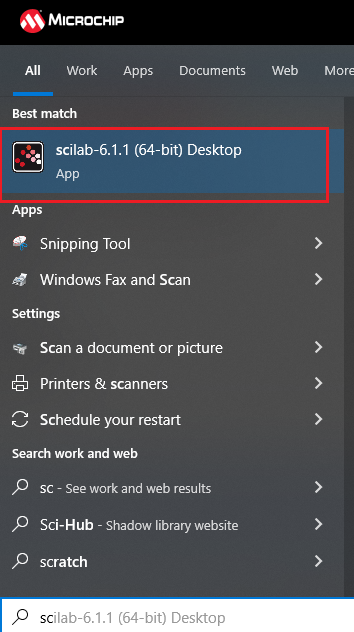
Open Scilab:
-
Navigate to Project Directory in Scilab:
Navigate to the project directory where the MPLAB Harmony 3 Project was saved: "<harmony 3 project path>\firmware\src\config\<config name>\X2Cmodel\"
-
Generate Code to Configure X2C Communicator Communication:
Open "basicModel.zcos"
Click on "Transform model and push to communicator"
Click on "Start Communicator"
Wait until you see "Model Set" in the log
Click on "Create Code" button
-
Add X2C Communicator API Calls to MPLAB Harmony 3 Project:
Add "X2C_Communicate()" API in the "while(1)" loop in "main.c"
Add "X2C_UpdateModel()" API as a callback to the TC0 period match interrupt
Start TC0 Timer
-
Make and Program Device Main Project:
Figure 1-10. Figure 15 - Build and Program Project 
-
Verify X2C Communicator Communication:
Click on "Start Communicator" (if not already open)
Set up Serial Port
Click on "Connect to Target"
Generating Code for Blinky LED Model in Scilab/Xcos + X2C
-
Save "X2C_Blinky_LED.zcos":
Save "X2C_BLINKY_LED.ZCOS" from "harmony 3 project path\x2c\X2Cmodel\X2C_BLINKY_LED.ZCOS" at "harmony 3 project path\firmware\src\config\config name\X2CCode\X2Cmodel\
Close any open instances of X2C Communicator
Open "X2C_Blinky_LED.zcos" in Scilab
Click on "Transform model and push to communicator"
Click on "Start Communicator"
Wait until you see "Model Set" in the log
Click on "Create Code" button
Updating "readInports" and "writeOutports" Function Calls in MPLABX Project
-
Open "X2C_Model.h":
Navigate to Source "Files -> config -> -> config name -> X2CModel ->X2Cmodel.h"
Update "X2C_InputPortsRead()" as shown below:
static inline void X2C_InputPortsRead(void) { if (BTN_S2_Get()) { x2cModel.inports.bBTN_S2 = 0; } else { x2cModel.inports.bBTN_S2 = 1; } } -
Update "X2C_OutputPortsWrite()":
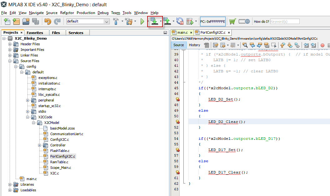
static inline void X2C_OutputPortsWrite(void) { if ((*x2cModel.outports.bLED_D2)) { LED_D2_Set(); } else { LED_D2_Clear(); } if ((*x2cModel.outports.bLED_D17)) { LED_D17_Set(); } else { LED_D17_Clear(); } } -
Make and Program Device with Updated Blinky LED Model:
Running the X2C_Blinky_LED Demo
Observe LED D2: It should turn ON when button switch S2 is pressed.
Live Update LED D17's Blink Rate:
Ensure X2C Communicator is connected
Increase/Decrease the Frequency input to the Sin3Gen block to adjust LED D17's blink rate in real-time
