
2 Getting Started
Unpack and inspect the kit carefully. The board is inside an enclosure made of ABS plastic UL 94 V-0 (150 mm x 80 mm x 50 mm).
The PL460-EK is a client board, so a host board with a specific firmware is necessary to use it. The PL460-EK must be connected to the host through the Xplained Pro connector (J2).
- When the DC Input connector (J4) is connected, the power LED shines green
- When the Xplained Pro connector (J2) is connected, the power LED shines green
For additional information about the power supply of PL460-EK, see Power Supply System. To connect a host or the AC/DC wall adapter to J4, it is not necessary to open the enclosure.
The PL460-EK requires a suitable cable to be connected from the connector J1 to the mains for the PLC communication. It is necessary to open the enclosure to connect an AC power source (mains grid) or a DC bus to the J1 connector (PLC output). Once the connection is made, remember to close the enclosure before connecting it to the mains.
To connect mains grid with the PLC communication, follow these steps to safely open the enclosure:
- Unscrew the four screws of the lid to
open the enclosure.
Figure 2-3. Unscrewing the Four Screws 
- Run the cables through the holes in
the enclosure.
Figure 2-4. Running the Cables - Take the 2-wire AC cable and connect
one wire to any terminal of the J1 connector (PLC+). Connect the other wire to the
other terminal of the J1 connector (PLC-). Then, screw the wires into the connector
securely.
Figure 2-5. Screwing Wires Into the Connector - Close the enclosure and screw the
four screws of the lid.
Figure 2-6. Screwing the Four Screws 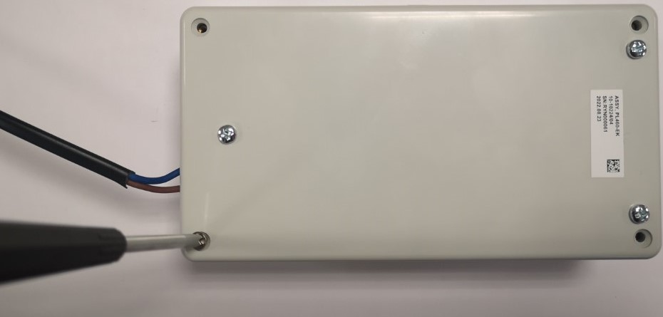
Once the enclosure is closed, the host can be connected to the board through the Xplained Pro connector, the AC/DC wall adapter can be connected to the mains grid, and the AC cable can be connected to the mains grid.
