2.9 MCLV 48V 300W Development Board Setup for SAME54 DIM
Setting Up the Hardware
The following table shows the target hardware for the application projects
Setting Up MCLV 48V 300W Development Board
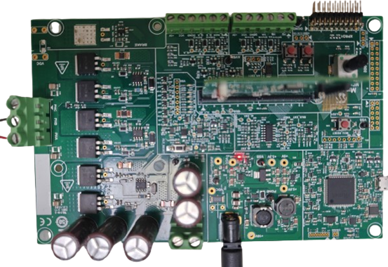
- Insert the SAME54 Motor
Control Dual In-Line Module on J8 interface header.

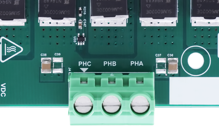
- Motor Connections: Connect
the 3 Phase connections of the motor on the J4 header

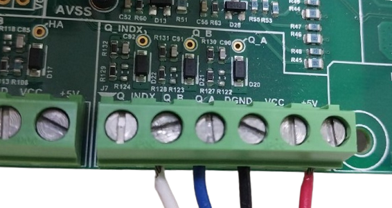
- Encoder Connections: Connect the QEA, QEB, 5V and GND connection as
shown.

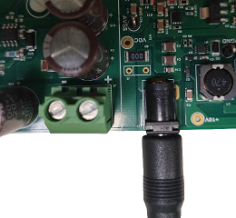
- Power the board with a 24V DC supply using J1 or J3(+,-) header. For
additional safety, it is recommended to use a current limited power supply
while testing this software demonstration on a non-default hardware and
motor.

- Complete Setup

Running the Application
- Build and Program the application using its IDE
- Press switch SW1 to start the motor
- Vary potentiometer to change the speed of the motor
- Press switch SW1 to stop the motor
- Press switch SW2 to change the direction of the motor
- Press switch SW1 again to start the motor
- Monitor graphs on X2C Scope
Refer to the following tables for switch and LED details:
| Switch | Description |
|---|---|
| Switch SW1 | To start or stop the motor. |
| Switch SW2 | To change the direction of
rotation. Direction toggle command is accepted only when motor is stationary. |
| LED D3 Status | Description |
|---|---|
| OFF | Motor spin direction is “positive”. |
| ON | Motor spin direction is “negative”. |
| LED D4 Status | Description |
|---|---|
| OFF | No fault. |
| ON | Fault is detected. |
