
3.5 I3C Target Driver
3.5.1 Introduction
The Improved Inter-Integrated Circuit (I3C) is a multi-Controller, two-wire serial data communication interface which builds upon the traditional Inter-Integrated Circuit (I2C) interface. It provides a fast, low-cost, low-power managed digital interface to improve sensor and device integration.
The MPLAB® Code Configurator (MCC) Melody I3C Target Driver supports generic protocol features of a I3C Target module, without Controller capabilities. The I3C Target Driver is further split into I3C Target DMA/Interrupt/Polling Driver based on the type of transmit and receive operation. This reference document covers the GUI configurations of I3C Target Driver and use cases which illustrates how I3C APIs can be used in application code. Refer to the links below to quick start on I3C Target Driver.
3.5.2 How to get started with I3C Target Driver
3.5.2.2 How to use I3C Target APIs
The I3C Target Driver requires a Peripheral Library (PLIB) dependency that is closely associated to an I3C hardware peripheral. The I3C Target PLIBs available on PIC® MCUs are listed below.
3.5.2 How to get started with I3C Target Driver
The below section explains the various GUI settings of the I3C Target Driver and its use case examples.
3.5.2.1 GUI Configurations of I3C Target Driver
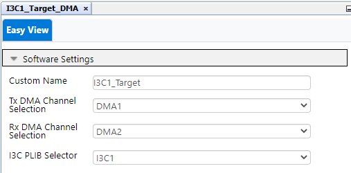
Basic Settings (I3C Target DMA Driver only)
- I3C Target DMA Driver supports
DMA-based transmit and receive operation. The user must select the desired DMA
channels for transmit and receive operation.
 Note: The code will not be generated if none of the DMA channels are available to use.
 - The DMA priority regarding the CPU execution can be set based on the application requirement using the DMA_I3C1_TX_DMAPrioritySet API for the transmit DMA and the DMA_I3C1_RX_DMAPrioritySet API for the receive DMA.
- The DMA channel settings are controlled by the I3C Target Driver. The user cannot change the DMA channel settings.
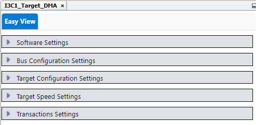
I3C Protocol & Target Settings (I3C Target DMA/Non-DMA Driver )
Settings related to the I3C protocol and the Target device can be configured using various UI settings available under the Bus Configuration settings, Target configuration settings, Target Speed Settings and Transaction Settings tab. Configure the settings based on the application requirements. These settings are common for the I3C Target DMA/Interrupt/Polling Driver
I3C PLIB Settings
I3C PLIB GUI has the settings specific to the I3C hardware peripheral. This includes clock selection for I3C peripheral, I3C pins buffer selection and the various system-level and module-level interrupt settings. The I3C Target PLIBs available on PIC® MCUs are listed below.
I3C PLIB for PIC18F-Q20 Device Family
Refer to the 4.16.3 How to Use the I3C PLIB for GUI configurations of I3C PLIB in PIC18F-Q20 family.
3.5.2.2 How to use I3C Target APIs
Refer to the examples below which showcase the usage of I3C APIs. Click the links to view the code snippets associated with each example.
Instructions common for all code snippets: 3.5.3.1.1 I3C Target Use Case Code Snippet Instructions
Transmit Message from Target to Controller (Private Read) : This example shows how to transmit data from the Target device to Controller.
Receive Message from Controller (Private Write) : This example shows how to receive data from the Controller.
Send In Band Interrupt (IBI) Request : This example shows how to send IBI.
Using Reset feature: This example shows how to use the I3C reset feature.
Send Hot Join Request: This example shows how to use send HJ request.
Using Bus Error feature: This example shows how to use the Bus Error feature.
Adding firmware support for unsupported CCCs: This example shows how to add firmware support for unsupported CCCs.
3.5.3 Module Documentation
3.5.3.1 I3C Target Driver Use Cases
This section explains various use cases of the I3C Target module. Refer to the examples to understand how to use I3C Target DMA driver APIs in user application.
This section explains various use cases of the I3C Target module. Refer to the examples to understand how to use I3C Target DMA driver APIs in user application.
3.5.3.1.1 I3C Target Use Case Code Snippet Instructions
Create a project and open MCC Melody. The configurations below are common for all examples.
-
Clock Control: Configure 64 MHz system clock
-
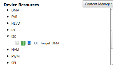
Add I3C_Target_DMA Driver from the I3C Driver to the project
-
Select I3C PLIB.
-
Configure the Custom Name as I3C_Target
-
Configure the respective DMA channels for transmit and receive operation.
-
-
Configure any other settings as needed by the example
-
Generate the code
-
Add the code snippet(s) to the application code. Call the application API in the main function as shown in the snippet below. If the interrupts are enabled in the example, then enable the Global Interrupt (GIE).
-
In case of DMA-based transmit and receive operation, the DMA priority regarding the CPU execution can be set based on the application requirement using the DMA_I3C1_TX_DMAPrioritySet API for the transmit DMA and the DMA_I3C1_RX_DMAPrioritySet API for the receive DMA.
#include "mcc_generated_files/system/system.h"
/*
    Main application
*/
int main(void)
{
    SYSTEM_Initialize();

    // If using interrupts in PIC18 High/Low Priority Mode you need to enable the Global High and Low Interrupts
    // If using interrupts in PIC Mid-Range Compatibility Mode you need to enable the Global Interrupts
    // Use the following macros to:

    // Enable the Global High Interrupts
    //INTERRUPT_GlobalInterruptHighEnable();

    // Disable the Global High Interrupts
    //INTERRUPT_GlobalInterruptHighDisable();

    // Enable the Global Low Interrupts
    //INTERRUPT_GlobalInterruptLowEnable();

    // Disable the Global Low Interrupts
    //INTERRUPT_GlobalInterruptLowDisable();

    I3CUseCase_API();

    while(1)
    {

    }

}
-
Program the board
3.5.3.1.2 Transmit Message from Target to Controller (Private Read)
This example shows how to transmit data from Target device to Controller.
Target device cannot initiate a transaction in case of Private Read. Target application can only keep the data ready to be transferred when requested by the Controller.
-
I3C Target Module must be operating in I3C mode.
uint8_t sendData[20] = {1,2,3,4,5,6,7,8,9,10,11,12,13,14,15,16,17,18,19,20};

void I3CUseCase_TransmitData(void)
{
    enum I3C_TARGET_BUFFER_TRANSMIT_ERROR sendError;

    //Register user callback for Transaction complete interrupt. This will be used to
    //know the status of data transmit operation.
    I3C_Target_TransactionCompleteCallbackRegister(TransactionCompleteCallback);

    //Setup to transmit 20 bytes of data
    sendError = I3C_Target_BufferTransmit(sendData, 20);

    if(sendError == I3C_TARGET_BUFFER_TRANSMIT_BUFFER_SIZE_EXCEEDED)
    {
        //software buffer size exceeded
    }
    else if(sendError == I3C_TARGET_BUFFER_TRANSMIT_NO_ERROR)
    {
        //No error during transmit setup
    }

}

void TransactionCompleteCallback(struct I3C_TARGET_TRANSACTION_COMPLETE_STATUS *transactionCompleteStatus)
{
    if(transactionCompleteStatus->dataFlowDirection == I3C_TARGET_DATA_TRANSMITTED)
    {
        //Data is transmitted

        //Check the error flags for error conditions occurred during last transaction
    }
}
The transaction complete interrupt is set when a Private/IBI transaction is completed. If multiple transaction occurs before the CPU executes the ISR handler, there is a chance to miss the transaction.
3.5.3.1.3 Receive Message from Controller (Private Write)
This example shows how to receive data from Controller.
This example uses Transaction Complete interrupt to detect the transaction completion. The transaction complete callback will give the status of transaction and the number of bytes received. I3C_Target_BufferReceive() must be called to configure the buffer for the next Private Write transaction.
It is recommended to NACK a Private Write transaction using I3C_Target_AllPrivateTransactionNACK() until the receive buffer is configured. Once the application configures the receive buffer, the next Private Write transaction can be ACKed using I3C_Target_NextPrivateTransactionACK() API.
-
I3C Target Module must be operating in I3C mode.
-
I3C Transaction Complete (module level interrupt), I3C General Interrupt (system level interrupt) and Global Interrupt must be enabled.
uint8_t receivedData[40]; //buffer to store received data
uint16_t numberOfBytesReceived;

void I3CUseCase_ReceiveData(void)
{
    enum I3C_TARGET_BUFFER_RECEIVE_ERROR receiveError;

    //Register user callback for Transaction Complete interrupt. This will be used to
    //know the status of data receive operation.
    I3C_Target_TransactionCompleteCallbackRegister(TransactionCompleteCallback);

    //Setup to receive 20 bytes of data
    receiveError = I3C_Target_BufferReceive(receivedData, 20);

    if (receiveError == I3C_TARGET_BUFFER_RECEIVE_BUFFER_SIZE_EXCEEDED)
    {
        //software buffer size exceeded
    }
    else if (receiveError == I3C_TARGET_BUFFER_RECEIVE_NO_ERROR)
    {
        //No error during receive setup
    }

    I3C_Target_NextPrivateTransactionACK();
}

void TransactionCompleteCallback(struct I3C_TARGET_TRANSACTION_COMPLETE_STATUS *transactionCompleteStatus)
{
    if(transactionCompleteStatus->dataFlowDirection == I3C_TARGET_DATA_RECEIVED)
    {
        //Data is received

        //Get number of bytes received during last transaction
        numberOfBytesReceived = transactionCompleteStatus->numOfBytesReceived;

        //Check the Receive Overrun and Buffer Overflow Error flags for error conditions occurred during last transaction

        //User can call I3C_Target_BufferReceive() here for next private write transaction
    }
}
The transaction complete interrupt is set when a Private/IBI transaction is completed. If multiple transaction occurs before the CPU executes the ISR handler, there is a chance to miss the transaction.
3.5.3.1.4 Send In-Band Interrupt (IBI) Request
This example shows how to send IBI.
-
I3C Target Module must be operating in I3C mode.
void I3CUseCase_IBI(void)
{
    enum I3C_TARGET_IBI_REQUEST_ERROR ibiError;
    uint8_t mandatoryByte = 0xAA;
    uint8_t payload[20] = {1,2,3,4,5,6,7,8,9,10,11,12,13,14,15,16,17,18,19,20}; //Without Mandatory Data Byte

    //Register user callback for IBI done interrupt. This will be used to
    //know the status of IBI process.
    I3C_Target_IBIDoneCallbackRegister(IBIDoneCallback);

    I3C_Target_IBIMandatoryDataByteSet(mandatoryByte);

    if(I3C_Target_IsIBIEnabledOnBus())
    {
        //Send IBI request
        ibiError = I3C_Target_IBIRequest(payload, 20);

        if(ibiError == I3C_TARGET_IBI_REQUEST_NOT_IN_I3C_MODE)
        {
            //Target is not in I3C mode
        }
        else if(ibiError == I3C_TARGET_IBI_REQUEST_IBI_DISABLED_ON_BUS)
        {
            //IBI is not enabled on the bus
        }
        else if(ibiError == I3C_TARGET_IBI_REQUEST_SEND_BUFFER_SIZE_EXCEEDED)
        {
            //Software buffer size exceeded
        }
        else if(ibiError == I3C_TARGET_IBI_REQUEST_NO_ERROR)
        {
            //No error during IBI request
        }
    }
}

void IBIDoneCallback(void)
{
    //IBI process is completed

    //Check the error flags for error conditions occurred during last transaction
}
IBI Done interrupt can be used to know the status of the IBI request.
3.5.3.1.5 Using Reset feature
This example shows how to use the I3C reset feature.
-
I3C Target Module must be operating in I3C mode.
-
I3C Reset (system level interrupt) and Global Interrupt must be enabled.
enum I3C_RESET_ACTION resetAction;
volatile bool resetPatternDetected = false;

void I3CUseCase_Reset(void)
{
    uint8_t resetCount = 0;

    //Register user callback for Reset action detected interrupt
    I3C_Target_ResetPatternDetectedCallbackRegister(ResetPatternDetectedCallback);

    while(1)
    {
        if(resetPatternDetected)
        {
            resetPatternDetected = false;

            if(resetAction == I3C_RESET_ACTION_NO_RESET)
            {
                resetCount = 0;

                //No action required to be taken
            }
            else if(resetAction == I3C_RESET_ACTION_RESET_PERIPHERAL)
            {
                resetCount = 0;

                //Perform software peripheral reset
                I3C_Target_PeripheralReset();

                I3C_Target_Initialize();

                I3C_Target_HotJoinRequest();
            }
            else if(resetAction == I3C_RESET_ACTION_RESET_WHOLE_TARGET)
            {
                resetCount = 0;

                //Soft reset of microcontroller
                RESET();
            }
            else if(resetAction == I3C_RESET_ACTION_NO_ACTION_SET)
            {
                if(resetCount == 0)
                {
                    //Reset Pattern detected w/o RSTACT for the first time
                    //Suggested user action is to reset the I3C module
                    resetCount++; // Increment counter

                    //Perform software peripheral reset
                    I3C_Target_PeripheralReset();

                    //It is suggested for the user to detect RSTACT or GETSTATUS CCC
                    //and reset the reset-count to 0 after the first reset as mentioned in the
                    //MIPI spec
                }
                else if(resetCount > 0)
                {
                    //Reset Pattern detected w/o RSTACT for the second time
                    //Suggested user action is to reset the whole device
                    //Note that the counter can be reset by user software if GETSTATUS CCC is received
                    resetCount = 0; // Reset counter

                    //Soft reset of microcontroller
                    RESET();
                }
            }
        }
    }
}

void ResetPatternDetectedCallback(void)
{
    resetPatternDetected = true;

    resetAction = I3C_Target_ResetActionGetAndClear();
}
3.5.3.1.6 Send Hot-Join Request
This example shows how to use the send HJ request.
-
I3C Target Module must be operating in I2C mode.
-
Hot Join capability must be enabled.
void I3CUseCase_HotJoinRequest(void)
{
    enum I3C_TARGET_OPERATING_MODE opMode;
    enum I3C_TARGET_HJ_REQUEST_ERROR hJRequestError;
    enum I3C_TARGET_HJ_STATUS;

    //Get operating mode
    opMode = I3C_Target_OperatingModeGet();

    //opMode should be either I2C_SDR or I2C_HDR

    if(I3C_Target_IsHotJoinEnabledOnBus())
    {
        //Request for Hot Join
        hJRequestError = I3C_Target_HotJoinRequest();

        if(hJRequestError == I3C_TARGET_HJ_REQUEST_NO_ERROR)
        {
            //No error while requesting Hot Join
        }
        else if(hJRequestError == I3C_TARGET_HJ_REQUEST_NOT_HJ_CAPABLE)
        {
            //Target is not HJ capable
        }
        else if(hJRequestError == I3C_TARGET_HJ_REQUEST_DYNAMIC_ADDRESS_ALREADY_ASSIGNED)
        {
            //Dynamic address has been already assigned
        }
        else if(hJRequestError == I3C_TARGET_HJ_REQUEST_HJ_DISABLED_ON_BUS)
        {
            //HJ is disabled on the bus
        }

        //Wait for Hot Join to complete
        while(I3C_Target_HotJoinStatusGet() == I3C_TARGET_HJ_PENDING);

        //Get operating mode
        opMode = I3C_Target_OperatingModeGet();

        //opMode should be either I3C_SDR or I3C_HDR
    }
}
3.5.3.1.7 Using Bus Error feature
This example shows how to use the Bus Error feature.
-
I3C Target Module must be operating in I3C mode.
-
I3C Bus error (module level interrupt), I3C error (system level interrupt) and Global interrupt must be enabled.
volatile uint8_t busErrorStatus;
volatile uint8_t busErrorReceived;

void I3CUseCase_BusError(void)
{
    //Register user callback for Bus error
    I3C_Target_BusErrorCallbackRegister(BusErrorCallback);

    while(1)
    {
        if(busErrorReceived)
        {
            busErrorReceived = false;

            if(busErrorStatus &= I3C_TARGET_BUS_TE0_ERROR)
            {
                //Perform required action as per the application
            }

            if(busErrorStatus &= I3C_TARGET_BUS_TE1_ERROR)
            {
                //Perform required action as per the application
            }

            if(busErrorStatus &= I3C_TARGET_BUS_TE2_ERROR)
            {
                //Perform required action as per the application
            }

            if(busErrorStatus &= I3C_TARGET_BUS_TE3_ERROR)
            {
                //Perform required action as per the application
            }

            if(busErrorStatus &= I3C_TARGET_BUS_TE4_ERROR)
            {
                //Perform required action as per the application
            }

            if(busErrorStatus &= I3C_TARGET_BUS_TE5_ERROR)
            {
                //Perform required action as per the application
            }

            if(busErrorStatus &= I3C_TARGET_BUS_TE6_ERROR)
            {
                //Perform required action as per the application
            }
        }
    }
}

void BusErrorCallback(void)
{
    busErrorReceived = true;

    busErrorStatus = I3C_Target_BusErrorStatusGetAndClear();
}
3.5.3.1.8 Adding firmware support for unsupported CCCs
This example shows how to add firmware support for unsupported CCCs.
-
I3C Target Module must be operating in I3C mode.
-
I3C Unsupported CCC (module level interrupt), I3C error (system level interrupt) and Global interrupt must be enabled.
volatile enum I3C_CCC receivedCCC;
volatile bool unsupportedCCCreceived = false;

void I3CUseCase_UsingUnsupportedCCC(void)
{
    //Register user callback for Unsupported CCC
    I3C_Target_UnsupportedCCCReceivedCallbackRegister(UnsupportedCCCReceivedCallback);

    while(1)
    {
        if(unsupportedCCCreceived)
        {
            unsupportedCCCreceived = false;

            switch(receivedCCC)
            {
                case I3C_CCC_ENTTM_D :
                    //Perform required action as per the application
                    break;

                case I3C_CCC_GETCAPS_D :
                    //Perform required action as per the application
                    break;

                case I3C_CCC_SETROUTE_D :
                    //Perform required action as per the application
                    break;
            }
        }
    }
}

void UnsupportedCCCReceivedCallback(void)
{
    unsupportedCCCreceived = true;

    receivedCCC = I3C1_LastCCCReceivedGet();
}
I3C Target Module stores CCC only and does not store defining byte(s) when unsupported CCC is received.
3.5.3.2 I3C Target Driver
This is the generated driver types header file for the I3C Target driver.
3.5.3.2.1 Module description
This is the generated driver types header file for the I3C Target driver.
Data structures
struct I3C_TARGET_TRANSACTION_COMPLETE_STATUS
Contains the status of the transaction complete operation.
Enumerations
enum I3C_TARGET_BUS_ERROR_STATUS { I3C_TARGET_BUS_TE0_ERROR = 1, I3C_TARGET_BUS_TE1_ERROR = 2, I3C_TARGET_BUS_TE2_ERROR = 4, I3C_TARGET_BUS_TE3_ERROR = 8, I3C_TARGET_BUS_TE4_ERROR = 16, I3C_TARGET_BUS_TE5_ERROR = 32, I3C_TARGET_BUS_TE6_ERROR = 64 }
Defines the different error states of I3C bus.
enum I3C_CCC { I3C_CCC_ENEC_B = 0x00, I3C_CCC_DISEC_B = 0x01, I3C_CCC_ENTAS0_B = 0x02, I3C_CCC_ENTAS1_B = 0x03, I3C_CCC_ENTAS2_B = 0x04, I3C_CCC_ENTAS3_B = 0x05, I3C_CCC_RSTDAA_B = 0x06, I3C_CCC_ENTDAA_B = 0x07, I3C_CCC_DEFTGTS_B = 0x08, I3C_CCC_SETMWL_B = 0x09, I3C_CCC_SETMRL_B = 0x0A, I3C_CCC_ENTTM_B = 0x0B, I3C_CCC_SETBUSCON_B = 0x0C, I3C_CCC_ENDXFER_B = 0x12, I3C_CCC_ENTHDR0_B = 0x20, I3C_CCC_ENTHDR1_B = 0x21, I3C_CCC_ENTHDR2_B = 0x22, I3C_CCC_ENTHDR3_B = 0x23, I3C_CCC_ENTHDR4_B = 0x24, I3C_CCC_ENTHDR5_B = 0x25, I3C_CCC_ENTHDR6_B = 0x26, I3C_CCC_ENTHDR7_B = 0x27, I3C_CCC_SETXTIME_B = 0x28, I3C_CCC_SETAASA_B = 0x29, I3C_CCC_RSTACT_B = 0x2A, I3C_CCC_DEFGRPA_B = 0x2B, I3C_CCC_RSTGRPA_B = 0x2C, I3C_CCC_MLANE_B = 0x2D, I3C_CCC_DBGACTION_B = 0x58, I3C_CCC_SETHID_B = 0x61, I3C_CCC_DEVCTRL_B = 0x62, I3C_CCC_ENEC_D = 0x80, I3C_CCC_DISEC_D = 0x81, I3C_CCC_ENTAS0_D = 0x82, I3C_CCC_ENTAS1_D = 0x83, I3C_CCC_ENTAS2_D = 0x84, I3C_CCC_ENTAS3_D = 0x85, I3C_CCC_RSTDAA_D = 0x86, I3C_CCC_SETDASA_D = 0x87, I3C_CCC_SETNEWDA_D = 0x88, I3C_CCC_SETMWL_D = 0x89, I3C_CCC_SETMRL_D = 0x8A, I3C_CCC_ENTTM_D = 0x8B, I3C_CCC_GETMRL_D = 0x8C, I3C_CCC_GETPID_D = 0x8D, I3C_CCC_GETBCR_D = 0x8E, I3C_CCC_GETDCR_D = 0x8F, I3C_CCC_GETSTATUS_D = 0x90, I3C_CCC_GETACCCR_D = 0x91, I3C_CCC_ENDXFER_D = 0x92, I3C_CCC_SETBRGTGT_D = 0x93, I3C_CCC_GETMXDS_D = 0x94, I3C_CCC_GETCAPS_D = 0x95, I3C_CCC_SETROUTE_D = 0x96, I3C_CCC_D2DXFER_D = 0x97, I3C_CCC_SETXTIME_D = 0x98, I3C_CCC_GETXTIME_D = 0x99, I3C_CCC_RSTACT_D = 0x9A, I3C_CCC_SETGRPA_D = 0x9B, I3C_CCC_RSTGRPA_D = 0x9C, I3C_CCC_MLANE_D = 0x9D, I3C_CCC_DBGOPCODE_D = 0xD7, I3C_CCC_DBGACTION_D = 0xD8, I3C_CCC_DEVCAPS_D = 0xE0 }
Defines the different Common Command Codes (CCCs) of I3C.
enum I3C_TARGET_OPERATING_MODE { I3C_TARGET_OPERATING_MODE_I2C_SDR = 0, I3C_TARGET_OPERATING_MODE_I3C_SDR = 1, I3C_TARGET_OPERATING_MODE_I2C_HDR = 2, I3C_TARGET_OPERATING_MODE_I3C_HDR = 3 }
Defines the operating modes of the I3C Target and bus.
enum I3C_RESET_ACTION { I3C_RESET_ACTION_NO_RESET = 0x00, I3C_RESET_ACTION_RESET_PERIPHERAL = 0x01, I3C_RESET_ACTION_RESET_WHOLE_TARGET = 0x02, I3C_RESET_ACTION_DEBUG_NETWORK_ADAPTER_RESET = 0x03, I3C_RESET_ACTION_VIRTUAL_TARGET_DETECT = 0x04, I3C_RESET_ACTION_RETURN_TIME_TO_RESET_PERIPHERAL = 0x81, I3C_RESET_ACTION_RETURN_TIME_TO_RESET_WHOLE_TARGET = 0x82, I3C_RESET_ACTION_RETURN_TIME_TO_DEBUG_NETWORK_ADAPTER_RESET = 0x83, I3C_RESET_ACTION_RETURN_VIRTUAL_TARGET_INDICATION = 0x84, I3C_RESET_ACTION_NO_ACTION_SET = 0xFF }
Defines the different reset actions based on the defining byte value of RSTACT CCC.
enum I3C_TARGET_IBI_REQUEST_ERROR { I3C_TARGET_IBI_REQUEST_NO_ERROR, I3C_TARGET_IBI_REQUEST_SEND_BUFFER_SIZE_EXCEEDED, I3C_TARGET_IBI_REQUEST_NOT_IN_I3C_MODE, I3C_TARGET_IBI_REQUEST_IBI_DISABLED_ON_BUS }
Defines the error states of the In-Band Interrupt request operation.
enum I3C_TARGET_HJ_REQUEST_ERROR { I3C_TARGET_HJ_REQUEST_NO_ERROR, I3C_TARGET_HJ_REQUEST_NOT_HJ_CAPABLE, I3C_TARGET_HJ_REQUEST_DYNAMIC_ADDRESS_ALREADY_ASSIGNED, I3C_TARGET_HJ_REQUEST_HJ_DISABLED_ON_BUS }
Defines the error states of the Hot-Join request operation.
enum I3C_TARGET_HJ_STATUS { I3C_TARGET_HJ_COMPLETED_OR_NOT_STARTED, I3C_TARGET_HJ_PENDING }
Defines the status of the Hot-Join operation.
enum I3C_TARGET_BUFFER_RECEIVE_ERROR { I3C_TARGET_BUFFER_RECEIVE_NO_ERROR, I3C_TARGET_BUFFER_RECEIVE_BUFFER_SIZE_EXCEEDED }
Defines the error status of the buffer receive operation.
enum I3C_TARGET_BUFFER_TRANSMIT_ERROR { I3C_TARGET_BUFFER_TRANSMIT_NO_ERROR, I3C_TARGET_BUFFER_TRANSMIT_BUFFER_SIZE_EXCEEDED }
Defines the error status of the buffer transmit operation.
enum I3C_TARGET_DATA_FLOW_DIRECTION { I3C_TARGET_DATA_TRANSMITTED, I3C_TARGET_DATA_RECEIVED }
Defines the data flow direction of an I3C transaction.
3.5.3.2.2 Enumeration Type Documentation
I3C_CCC
enum I3C_CCC
Defines the different Common Command Codes (CCCs) of I3C.
| I3C_CCC_ENEC_B |
Enable Events Command |
| I3C_CCC_DISEC_B |
Disable Events Command |
| I3C_CCC_ENTAS0_B |
Enter Activity State 0 |
| I3C_CCC_ENTAS1_B |
Enter Activity State 1 |
| I3C_CCC_ENTAS2_B |
Enter Activity State 2 |
| I3C_CCC_ENTAS3_B |
Enter Activity State 3 |
| I3C_CCC_RSTDAA_B |
Reset Dynamic Address Assignment |
| I3C_CCC_ENTDAA_B |
Enter Dynamic Address Assignment |
| I3C_CCC_DEFTGTS_B |
Define List of Targets |
| I3C_CCC_SETMWL_B |
Set Max Write Length |
| I3C_CCC_SETMRL_B |
Set Max Read Length |
| I3C_CCC_ENTTM_B |
Enter Test Mode |
| I3C_CCC_SETBUSCON_B |
Set Bus Context |
| I3C_CCC_ENDXFER_B |
Data Transfer Ending Procedure Control |
| I3C_CCC_ENTHDR0_B |
Enter HDR Mode 0 |
| I3C_CCC_ENTHDR1_B |
Enter HDR Mode 1 |
| I3C_CCC_ENTHDR2_B |
Enter HDR Mode 2 |
| I3C_CCC_ENTHDR3_B |
Enter HDR Mode 3 |
| I3C_CCC_ENTHDR4_B |
Enter HDR Mode 4 |
| I3C_CCC_ENTHDR5_B |
Enter HDR Mode 5 |
| I3C_CCC_ENTHDR6_B |
Enter HDR Mode 6 |
| I3C_CCC_ENTHDR7_B |
Enter HDR Mode 7 |
| I3C_CCC_SETXTIME_B |
Exchange Timing Information |
| I3C_CCC_SETAASA_B |
Set All Addresses to Static Addresses |
| I3C_CCC_RSTACT_B |
Target Reset Action |
| I3C_CCC_DEFGRPA_B |
Define List of Group Address |
| I3C_CCC_RSTGRPA_B |
Reset Group Address |
| I3C_CCC_MLANE_B |
Multi-Lane Data Transfer Control |
| I3C_CCC_DBGACTION_B |
Debug Action (Debug Specific command) |
| I3C_CCC_SETHID_B |
Hub updates 3-bit HID field (JEDEC Specific command) |
| I3C_CCC_DEVCTRL_B |
Configure hub and all devices behind hub (JEDEC Specific command) |
| I3C_CCC_ENEC_D |
Enable Events Command |
| I3C_CCC_DISEC_D |
Disable Events Command |
| I3C_CCC_ENTAS0_D |
Enter Activity State 0 |
| I3C_CCC_ENTAS1_D |
Enter Activity State 1 |
| I3C_CCC_ENTAS2_D |
Enter Activity State 2 |
| I3C_CCC_ENTAS3_D |
Enter Activity State 3 |
| I3C_CCC_RSTDAA_D |
Reset Dynamic Address Assignment |
| I3C_CCC_SETDASA_D |
Set Dynamic Address from Static Address |
| I3C_CCC_SETNEWDA_D |
Set New Dynamic Address |
| I3C_CCC_SETMWL_D |
Set Max Write Length |
| I3C_CCC_SETMRL_D |
Set Max Read Length |
| I3C_CCC_ENTTM_D |
Enter Test Mode |
| I3C_CCC_GETMRL_D |
Get Max Read Length |
| I3C_CCC_GETPID_D |
Get Provisioned ID |
| I3C_CCC_GETBCR_D |
Get Bus Characteristics Register |
| I3C_CCC_GETDCR_D |
Get Device Characteristics Register |
| I3C_CCC_GETSTATUS_D |
Get Device Status |
| I3C_CCC_GETACCCR_D |
Get Accept Controller Role |
| I3C_CCC_ENDXFER_D |
Data Transfer Ending Procedure Control |
| I3C_CCC_SETBRGTGT_D |
Set Bridge Targets |
| I3C_CCC_GETMXDS_D |
Get Max Data Speed |
| I3C_CCC_GETCAPS_D |
Get Optional Feature Capabilities |
| I3C_CCC_SETROUTE_D |
Set Route |
| I3C_CCC_D2DXFER_D |
Device to Device(s) Tunneling Control |
| I3C_CCC_SETXTIME_D |
Set Exchange Timing Information |
| I3C_CCC_GETXTIME_D |
Get Exchange Timing Information |
| I3C_CCC_RSTACT_D |
Target Reset Action |
| I3C_CCC_SETGRPA_D |
Set Group Address |
| I3C_CCC_RSTGRPA_D |
Reset Group Address |
| I3C_CCC_MLANE_D |
Multi-Lane Data Transfer Control |
| I3C_CCC_DBGOPCODE_D |
Debug Network Adaptor Operation (Debug Specific command) |
| I3C_CCC_DBGACTION_D |
Debug Action (Debug Specific command) |
| I3C_CCC_DEVCAPS_D |
Get device capabilities (JEDEC Specific command) |
I3C_RESET_ACTION
enum I3C_RESET_ACTION
Defines the different reset actions based on the defining byte value of RSTACT CCC.
| I3C_RESET_ACTION_NO_RESET | |
| I3C_RESET_ACTION_RESET_PERIPHERAL | |
| I3C_RESET_ACTION_RESET_WHOLE_TARGET | |
| I3C_RESET_ACTION_DEBUG_NETWORK_ADAPTER_RESET | |
| I3C_RESET_ACTION_VIRTUAL_TARGET_DETECT | |
| I3C_RESET_ACTION_RETURN_TIME_TO_RESET_PERIPHERAL | |
| I3C_RESET_ACTION_RETURN_TIME_TO_RESET_WHOLE_TARGET | |
| I3C_RESET_ACTION_RETURN_TIME_TO_DEBUG_NETWORK_ADAPTER_RESET | |
| I3C_RESET_ACTION_RETURN_VIRTUAL_TARGET_INDICATION | |
| I3C_RESET_ACTION_NO_ACTION_SET |
I3C_TARGET_BUFFER_RECEIVE_ERROR
enum I3C_TARGET_BUFFER_RECEIVE_ERROR
Defines the error status of the buffer receive operation.
| I3C_TARGET_BUFFER_RECEIVE_NO_ERROR | |
| I3C_TARGET_BUFFER_RECEIVE_BUFFER_SIZE_EXCEEDED |
I3C_TARGET_BUFFER_TRANSMIT_ERROR
enum I3C_TARGET_BUFFER_TRANSMIT_ERROR
Defines the error status of the buffer transmit operation.
| I3C_TARGET_BUFFER_TRANSMIT_NO_ERROR | |
| I3C_TARGET_BUFFER_TRANSMIT_BUFFER_SIZE_EXCEEDED |
I3C_TARGET_BUS_ERROR_STATUS
enum I3C_TARGET_BUS_ERROR_STATUS
Defines the different error states of I3C bus.
| I3C_TARGET_BUS_TE0_ERROR |
Invalid Broadcast Address or Dynamic Address |
| I3C_TARGET_BUS_TE1_ERROR |
Invalid CCC Code |
| I3C_TARGET_BUS_TE2_ERROR |
Invalid Write Data |
| I3C_TARGET_BUS_TE3_ERROR |
Invalid Assigned Address during the Dynamic Address Assignment |
| I3C_TARGET_BUS_TE4_ERROR |
Illegally formatted data during Dynamic Address Assignment |
| I3C_TARGET_BUS_TE5_ERROR |
Illegally formatted CCC frame |
| I3C_TARGET_BUS_TE6_ERROR |
Corrupted R/W during Private Transfer |
I3C_TARGET_DATA_FLOW_DIRECTION
enum I3C_TARGET_DATA_FLOW_DIRECTION
Defines the data flow direction of an I3C transaction.
| I3C_TARGET_DATA_TRANSMITTED |
Data transmitted via Private Read or In-Band Interrupt transaction |
| I3C_TARGET_DATA_RECEIVED |
Data received via Private Write transaction |
I3C_TARGET_HJ_REQUEST_ERROR
enum I3C_TARGET_HJ_REQUEST_ERROR
Defines the error states of the Hot-Join request operation.
| I3C_TARGET_HJ_REQUEST_NO_ERROR | |
| I3C_TARGET_HJ_REQUEST_NOT_HJ_CAPABLE | |
| I3C_TARGET_HJ_REQUEST_DYNAMIC_ADDRESS_ALREADY_ASSIGNED | |
| I3C_TARGET_HJ_REQUEST_HJ_DISABLED_ON_BUS |
I3C_TARGET_HJ_STATUS
enum I3C_TARGET_HJ_STATUS
Defines the status of the Hot-Join operation.
| I3C_TARGET_HJ_COMPLETED_OR_NOT_STARTED | |
| I3C_TARGET_HJ_PENDING |
I3C_TARGET_IBI_REQUEST_ERROR
enum I3C_TARGET_IBI_REQUEST_ERROR
Defines the error states of the In-Band Interrupt request operation.
| I3C_TARGET_IBI_REQUEST_NO_ERROR | |
| I3C_TARGET_IBI_REQUEST_SEND_BUFFER_SIZE_EXCEEDED | |
| I3C_TARGET_IBI_REQUEST_NOT_IN_I3C_MODE | |
| I3C_TARGET_IBI_REQUEST_IBI_DISABLED_ON_BUS |
I3C_TARGET_OPERATING_MODE
enum I3C_TARGET_OPERATING_MODE
Defines the operating modes of the I3C Target and bus.
| I3C_TARGET_OPERATING_MODE_I2C_SDR |
The Target is operating in Legacy I2C mode; The bus is operating in Single Data Rate (SDR) mode |
| I3C_TARGET_OPERATING_MODE_I3C_SDR |
The Target is operating in I3C mode; The bus is operating in Single Data Rate (SDR) mode |
| I3C_TARGET_OPERATING_MODE_I2C_HDR |
The Target is operating in Legacy I2C mode; The bus is operating in High Data Rate (HDR) mode |
| I3C_TARGET_OPERATING_MODE_I3C_HDR |
The Target is operating in I3C mode; The bus is operating in High Data Rate (HDR) mode |
3.5.4 Class Documentation
3.5.4.1 I3C_TARGET_TRANSACTION_COMPLETE_STATUS Struct Reference
Contains the status of the transaction complete operation.
3.5.4.1.1 Detailed Description
Contains the status of the transaction complete operation.
#include <i3c_target_types.h>
Public Attributes
3.5.4.1.2 Member Data Documentation
dataFlowDirection
enum I3C_TARGET_DATA_FLOW_DIRECTION dataFlowDirection
numOfBytesReceived
uint16_t numOfBytesReceived
3.5.5 File Documentation
3.5.5.1 source/i3c_examples.dox File Reference
3.5.5.2 source/i3c_target_types.h File Reference
#include <stdint.h>
3.5.5.2.1 Data structures
struct I3C_TARGET_TRANSACTION_COMPLETE_STATUS
Contains the status of the transaction complete operation.
3.5.5.2.2 Enumerations
enum I3C_TARGET_BUS_ERROR_STATUS { I3C_TARGET_BUS_TE0_ERROR = 1, I3C_TARGET_BUS_TE1_ERROR = 2, I3C_TARGET_BUS_TE2_ERROR = 4, I3C_TARGET_BUS_TE3_ERROR = 8, I3C_TARGET_BUS_TE4_ERROR = 16, I3C_TARGET_BUS_TE5_ERROR = 32, I3C_TARGET_BUS_TE6_ERROR = 64 }
Defines the different error states of I3C bus.
enum I3C_CCC { I3C_CCC_ENEC_B = 0x00, I3C_CCC_DISEC_B = 0x01, I3C_CCC_ENTAS0_B = 0x02, I3C_CCC_ENTAS1_B = 0x03, I3C_CCC_ENTAS2_B = 0x04, I3C_CCC_ENTAS3_B = 0x05, I3C_CCC_RSTDAA_B = 0x06, I3C_CCC_ENTDAA_B = 0x07, I3C_CCC_DEFTGTS_B = 0x08, I3C_CCC_SETMWL_B = 0x09, I3C_CCC_SETMRL_B = 0x0A, I3C_CCC_ENTTM_B = 0x0B, I3C_CCC_SETBUSCON_B = 0x0C, I3C_CCC_ENDXFER_B = 0x12, I3C_CCC_ENTHDR0_B = 0x20, I3C_CCC_ENTHDR1_B = 0x21, I3C_CCC_ENTHDR2_B = 0x22, I3C_CCC_ENTHDR3_B = 0x23, I3C_CCC_ENTHDR4_B = 0x24, I3C_CCC_ENTHDR5_B = 0x25, I3C_CCC_ENTHDR6_B = 0x26, I3C_CCC_ENTHDR7_B = 0x27, I3C_CCC_SETXTIME_B = 0x28, I3C_CCC_SETAASA_B = 0x29, I3C_CCC_RSTACT_B = 0x2A, I3C_CCC_DEFGRPA_B = 0x2B, I3C_CCC_RSTGRPA_B = 0x2C, I3C_CCC_MLANE_B = 0x2D, I3C_CCC_DBGACTION_B = 0x58, I3C_CCC_SETHID_B = 0x61, I3C_CCC_DEVCTRL_B = 0x62, I3C_CCC_ENEC_D = 0x80, I3C_CCC_DISEC_D = 0x81, I3C_CCC_ENTAS0_D = 0x82, I3C_CCC_ENTAS1_D = 0x83, I3C_CCC_ENTAS2_D = 0x84, I3C_CCC_ENTAS3_D = 0x85, I3C_CCC_RSTDAA_D = 0x86, I3C_CCC_SETDASA_D = 0x87, I3C_CCC_SETNEWDA_D = 0x88, I3C_CCC_SETMWL_D = 0x89, I3C_CCC_SETMRL_D = 0x8A, I3C_CCC_ENTTM_D = 0x8B, I3C_CCC_GETMRL_D = 0x8C, I3C_CCC_GETPID_D = 0x8D, I3C_CCC_GETBCR_D = 0x8E, I3C_CCC_GETDCR_D = 0x8F, I3C_CCC_GETSTATUS_D = 0x90, I3C_CCC_GETACCCR_D = 0x91, I3C_CCC_ENDXFER_D = 0x92, I3C_CCC_SETBRGTGT_D = 0x93, I3C_CCC_GETMXDS_D = 0x94, I3C_CCC_GETCAPS_D = 0x95, I3C_CCC_SETROUTE_D = 0x96, I3C_CCC_D2DXFER_D = 0x97, I3C_CCC_SETXTIME_D = 0x98, I3C_CCC_GETXTIME_D = 0x99, I3C_CCC_RSTACT_D = 0x9A, I3C_CCC_SETGRPA_D = 0x9B, I3C_CCC_RSTGRPA_D = 0x9C, I3C_CCC_MLANE_D = 0x9D, I3C_CCC_DBGOPCODE_D = 0xD7, I3C_CCC_DBGACTION_D = 0xD8, I3C_CCC_DEVCAPS_D = 0xE0 }
Defines the different Common Command Codes (CCCs) of I3C.
enum I3C_TARGET_OPERATING_MODE { I3C_TARGET_OPERATING_MODE_I2C_SDR = 0, I3C_TARGET_OPERATING_MODE_I3C_SDR = 1, I3C_TARGET_OPERATING_MODE_I2C_HDR = 2, I3C_TARGET_OPERATING_MODE_I3C_HDR = 3 }
Defines the operating modes of the I3C Target and bus.
enum I3C_RESET_ACTION { I3C_RESET_ACTION_NO_RESET = 0x00, I3C_RESET_ACTION_RESET_PERIPHERAL = 0x01, I3C_RESET_ACTION_RESET_WHOLE_TARGET = 0x02, I3C_RESET_ACTION_DEBUG_NETWORK_ADAPTER_RESET = 0x03, I3C_RESET_ACTION_VIRTUAL_TARGET_DETECT = 0x04, I3C_RESET_ACTION_RETURN_TIME_TO_RESET_PERIPHERAL = 0x81, I3C_RESET_ACTION_RETURN_TIME_TO_RESET_WHOLE_TARGET = 0x82, I3C_RESET_ACTION_RETURN_TIME_TO_DEBUG_NETWORK_ADAPTER_RESET = 0x83, I3C_RESET_ACTION_RETURN_VIRTUAL_TARGET_INDICATION = 0x84, I3C_RESET_ACTION_NO_ACTION_SET = 0xFF }
Defines the different reset actions based on the defining byte value of RSTACT CCC.
enum I3C_TARGET_IBI_REQUEST_ERROR { I3C_TARGET_IBI_REQUEST_NO_ERROR, I3C_TARGET_IBI_REQUEST_SEND_BUFFER_SIZE_EXCEEDED, I3C_TARGET_IBI_REQUEST_NOT_IN_I3C_MODE, I3C_TARGET_IBI_REQUEST_IBI_DISABLED_ON_BUS }
Defines the error states of the In-Band Interrupt request operation.
enum I3C_TARGET_HJ_REQUEST_ERROR { I3C_TARGET_HJ_REQUEST_NO_ERROR, I3C_TARGET_HJ_REQUEST_NOT_HJ_CAPABLE, I3C_TARGET_HJ_REQUEST_DYNAMIC_ADDRESS_ALREADY_ASSIGNED, I3C_TARGET_HJ_REQUEST_HJ_DISABLED_ON_BUS }
Defines the error states of the Hot-Join request operation.
enum I3C_TARGET_HJ_STATUS { I3C_TARGET_HJ_COMPLETED_OR_NOT_STARTED, I3C_TARGET_HJ_PENDING }
Defines the status of the Hot-Join operation.
enum I3C_TARGET_BUFFER_RECEIVE_ERROR { I3C_TARGET_BUFFER_RECEIVE_NO_ERROR, I3C_TARGET_BUFFER_RECEIVE_BUFFER_SIZE_EXCEEDED }
Defines the error status of the buffer receive operation.
enum I3C_TARGET_BUFFER_TRANSMIT_ERROR { I3C_TARGET_BUFFER_TRANSMIT_NO_ERROR, I3C_TARGET_BUFFER_TRANSMIT_BUFFER_SIZE_EXCEEDED }
Defines the error status of the buffer transmit operation.
enum I3C_TARGET_DATA_FLOW_DIRECTION { I3C_TARGET_DATA_TRANSMITTED, I3C_TARGET_DATA_RECEIVED }
Defines the data flow direction of an I3C transaction.
3.5.5.2.3 Detailed Description
This is the generated driver types header file for the I3C Target driver.
I3C Generated Driver Types Header File
3.5.5.2.4 Enumeration Type Documentation
I3C_CCC
enum I3C_CCC
Defines the different Common Command Codes (CCCs) of I3C.
| I3C_CCC_ENEC_B |
Enable Events Command |
| I3C_CCC_DISEC_B |
Disable Events Command |
| I3C_CCC_ENTAS0_B |
Enter Activity State 0 |
| I3C_CCC_ENTAS1_B |
Enter Activity State 1 |
| I3C_CCC_ENTAS2_B |
Enter Activity State 2 |
| I3C_CCC_ENTAS3_B |
Enter Activity State 3 |
| I3C_CCC_RSTDAA_B |
Reset Dynamic Address Assignment |
| I3C_CCC_ENTDAA_B |
Enter Dynamic Address Assignment |
| I3C_CCC_DEFTGTS_B |
Define List of Targets |
| I3C_CCC_SETMWL_B |
Set Max Write Length |
| I3C_CCC_SETMRL_B |
Set Max Read Length |
| I3C_CCC_ENTTM_B |
Enter Test Mode |
| I3C_CCC_SETBUSCON_B |
Set Bus Context |
| I3C_CCC_ENDXFER_B |
Data Transfer Ending Procedure Control |
| I3C_CCC_ENTHDR0_B |
Enter HDR Mode 0 |
| I3C_CCC_ENTHDR1_B |
Enter HDR Mode 1 |
| I3C_CCC_ENTHDR2_B |
Enter HDR Mode 2 |
| I3C_CCC_ENTHDR3_B |
Enter HDR Mode 3 |
| I3C_CCC_ENTHDR4_B |
Enter HDR Mode 4 |
| I3C_CCC_ENTHDR5_B |
Enter HDR Mode 5 |
| I3C_CCC_ENTHDR6_B |
Enter HDR Mode 6 |
| I3C_CCC_ENTHDR7_B |
Enter HDR Mode 7 |
| I3C_CCC_SETXTIME_B |
Exchange Timing Information |
| I3C_CCC_SETAASA_B |
Set All Addresses to Static Addresses |
| I3C_CCC_RSTACT_B |
Target Reset Action |
| I3C_CCC_DEFGRPA_B |
Define List of Group Address |
| I3C_CCC_RSTGRPA_B |
Reset Group Address |
| I3C_CCC_MLANE_B |
Multi-Lane Data Transfer Control |
| I3C_CCC_DBGACTION_B |
Debug Action (Debug Specific command) |
| I3C_CCC_SETHID_B |
Hub updates 3-bit HID field (JEDEC Specific command) |
| I3C_CCC_DEVCTRL_B |
Configure hub and all devices behind hub (JEDEC Specific command) |
| I3C_CCC_ENEC_D |
Enable Events Command |
| I3C_CCC_DISEC_D |
Disable Events Command |
| I3C_CCC_ENTAS0_D |
Enter Activity State 0 |
| I3C_CCC_ENTAS1_D |
Enter Activity State 1 |
| I3C_CCC_ENTAS2_D |
Enter Activity State 2 |
| I3C_CCC_ENTAS3_D |
Enter Activity State 3 |
| I3C_CCC_RSTDAA_D |
Reset Dynamic Address Assignment |
| I3C_CCC_SETDASA_D |
Set Dynamic Address from Static Address |
| I3C_CCC_SETNEWDA_D |
Set New Dynamic Address |
| I3C_CCC_SETMWL_D |
Set Max Write Length |
| I3C_CCC_SETMRL_D |
Set Max Read Length |
| I3C_CCC_ENTTM_D |
Enter Test Mode |
| I3C_CCC_GETMRL_D |
Get Max Read Length |
| I3C_CCC_GETPID_D |
Get Provisioned ID |
| I3C_CCC_GETBCR_D |
Get Bus Characteristics Register |
| I3C_CCC_GETDCR_D |
Get Device Characteristics Register |
| I3C_CCC_GETSTATUS_D |
Get Device Status |
| I3C_CCC_GETACCCR_D |
Get Accept Controller Role |
| I3C_CCC_ENDXFER_D |
Data Transfer Ending Procedure Control |
| I3C_CCC_SETBRGTGT_D |
Set Bridge Targets |
| I3C_CCC_GETMXDS_D |
Get Max Data Speed |
| I3C_CCC_GETCAPS_D |
Get Optional Feature Capabilities |
| I3C_CCC_SETROUTE_D |
Set Route |
| I3C_CCC_D2DXFER_D |
Device to Device(s) Tunneling Control |
| I3C_CCC_SETXTIME_D |
Set Exchange Timing Information |
| I3C_CCC_GETXTIME_D |
Get Exchange Timing Information |
| I3C_CCC_RSTACT_D |
Target Reset Action |
| I3C_CCC_SETGRPA_D |
Set Group Address |
| I3C_CCC_RSTGRPA_D |
Reset Group Address |
| I3C_CCC_MLANE_D |
Multi-Lane Data Transfer Control |
| I3C_CCC_DBGOPCODE_D |
Debug Network Adaptor Operation (Debug Specific command) |
| I3C_CCC_DBGACTION_D |
Debug Action (Debug Specific command) |
| I3C_CCC_DEVCAPS_D |
Get device capabilities (JEDEC Specific command) |
I3C_RESET_ACTION
enum I3C_RESET_ACTION
Defines the different reset actions based on the defining byte value of RSTACT CCC.
| I3C_RESET_ACTION_NO_RESET | |
| I3C_RESET_ACTION_RESET_PERIPHERAL | |
| I3C_RESET_ACTION_RESET_WHOLE_TARGET | |
| I3C_RESET_ACTION_DEBUG_NETWORK_ADAPTER_RESET | |
| I3C_RESET_ACTION_VIRTUAL_TARGET_DETECT | |
| I3C_RESET_ACTION_RETURN_TIME_TO_RESET_PERIPHERAL | |
| I3C_RESET_ACTION_RETURN_TIME_TO_RESET_WHOLE_TARGET | |
| I3C_RESET_ACTION_RETURN_TIME_TO_DEBUG_NETWORK_ADAPTER_RESET | |
| I3C_RESET_ACTION_RETURN_VIRTUAL_TARGET_INDICATION | |
| I3C_RESET_ACTION_NO_ACTION_SET |
I3C_TARGET_BUFFER_RECEIVE_ERROR
enum I3C_TARGET_BUFFER_RECEIVE_ERROR
Defines the error status of the buffer receive operation.
| I3C_TARGET_BUFFER_RECEIVE_NO_ERROR | |
| I3C_TARGET_BUFFER_RECEIVE_BUFFER_SIZE_EXCEEDED |
I3C_TARGET_BUFFER_TRANSMIT_ERROR
enum I3C_TARGET_BUFFER_TRANSMIT_ERROR
Defines the error status of the buffer transmit operation.
| I3C_TARGET_BUFFER_TRANSMIT_NO_ERROR | |
| I3C_TARGET_BUFFER_TRANSMIT_BUFFER_SIZE_EXCEEDED |
I3C_TARGET_BUS_ERROR_STATUS
enum I3C_TARGET_BUS_ERROR_STATUS
Defines the different error states of I3C bus.
| I3C_TARGET_BUS_TE0_ERROR |
Invalid Broadcast Address or Dynamic Address |
| I3C_TARGET_BUS_TE1_ERROR |
Invalid CCC Code |
| I3C_TARGET_BUS_TE2_ERROR |
Invalid Write Data |
| I3C_TARGET_BUS_TE3_ERROR |
Invalid Assigned Address during the Dynamic Address Assignment |
| I3C_TARGET_BUS_TE4_ERROR |
Illegally formatted data during Dynamic Address Assignment |
| I3C_TARGET_BUS_TE5_ERROR |
Illegally formatted CCC frame |
| I3C_TARGET_BUS_TE6_ERROR |
Corrupted R/W during Private Transfer |
I3C_TARGET_DATA_FLOW_DIRECTION
enum I3C_TARGET_DATA_FLOW_DIRECTION
Defines the data flow direction of an I3C transaction.
| I3C_TARGET_DATA_TRANSMITTED |
Data transmitted via Private Read or In-Band Interrupt transaction |
| I3C_TARGET_DATA_RECEIVED |
Data received via Private Write transaction |
I3C_TARGET_HJ_REQUEST_ERROR
enum I3C_TARGET_HJ_REQUEST_ERROR
Defines the error states of the Hot-Join request operation.
| I3C_TARGET_HJ_REQUEST_NO_ERROR | |
| I3C_TARGET_HJ_REQUEST_NOT_HJ_CAPABLE | |
| I3C_TARGET_HJ_REQUEST_DYNAMIC_ADDRESS_ALREADY_ASSIGNED | |
| I3C_TARGET_HJ_REQUEST_HJ_DISABLED_ON_BUS |
I3C_TARGET_HJ_STATUS
enum I3C_TARGET_HJ_STATUS
Defines the status of the Hot-Join operation.
| I3C_TARGET_HJ_COMPLETED_OR_NOT_STARTED | |
| I3C_TARGET_HJ_PENDING |
I3C_TARGET_IBI_REQUEST_ERROR
enum I3C_TARGET_IBI_REQUEST_ERROR
Defines the error states of the In-Band Interrupt request operation.
| I3C_TARGET_IBI_REQUEST_NO_ERROR | |
| I3C_TARGET_IBI_REQUEST_SEND_BUFFER_SIZE_EXCEEDED | |
| I3C_TARGET_IBI_REQUEST_NOT_IN_I3C_MODE | |
| I3C_TARGET_IBI_REQUEST_IBI_DISABLED_ON_BUS |
I3C_TARGET_OPERATING_MODE
enum I3C_TARGET_OPERATING_MODE
Defines the operating modes of the I3C Target and bus.
| I3C_TARGET_OPERATING_MODE_I2C_SDR |
The Target is operating in Legacy I2C mode; The bus is operating in Single Data Rate (SDR) mode |
| I3C_TARGET_OPERATING_MODE_I3C_SDR |
The Target is operating in I3C mode; The bus is operating in Single Data Rate (SDR) mode |
| I3C_TARGET_OPERATING_MODE_I2C_HDR |
The Target is operating in Legacy I2C mode; The bus is operating in High Data Rate (HDR) mode |
| I3C_TARGET_OPERATING_MODE_I3C_HDR |
The Target is operating in I3C mode; The bus is operating in High Data Rate (HDR) mode |