
4.24.1.2 8/16-bit TMR0
8/16-bit Timer0
4.24.1.2.1 Introduction
The Timer0 (TMR0) module is a flexible 8/16-bit timer with configurable time-out period.
4.24.1.2.2 Supported Device Families
| PIC12/16F184x | PIC16F152xx | PIC16F153xx |
| PIC16F171x | PIC16F171xx | PIC16F180xx |
| PIC16F181xx | PIC16F183xx | PIC16F184xx |
| PIC16F188xx | PIC16F191xx | PIC18F-K20 |
| PIC18F-K22 | PIC18F-K40 | PIC18F-K42 |
| PIC18F-K50 | PIC18F-K80 | PIC18F-K83 |
| PIC18F-K90 | PIC18F-Q10 | PIC18F-Q20 |
| PIC18F-Q40 | PIC18F-Q41 | PIC18F-Q43 |
| PIC18F-Q71 | PIC18F-Q83 | PIC18F-Q84 |
4.24.1.2.3 Timer Interface
-
struct TMR_INTERFACE
Structure containing the function pointers of the TMR driver.
4.24.1.2.4 Required header files:
#include "mcc_generated_files/timer/tmr0.h"4.24.1.2.5 How to Use the Timer0 PLIB Driver
The links below provide examples for different use cases of the Timer0 (TMR0) Peripheral Library (PLIB) driver.
For general instructions common to all examples, refer to this section: 4.24.1.2.9.1.1 Timer Use Case Code Snippet Instructions
- 4.24.1.2.9.1.2 Timer Use Case 1: 100 ms Timer: This use-case configures Timer0 (TMR0) in 8-bit mode to generate an overflow interrupt at a period of 100ms, toggling a LED at this period.
- 4.24.1.2.9.1.3 Timer Use Case 2: Timer Switch Frequency 100 ms / 500 ms: This use case sets up a project which changes the time-out period between 100 ms and 500 ms, when a switch is pressed.
- 4.24.1.2.9.1.4 Timer Use Case 3: Timer Wake From Sleep Every 10s: This use case configures Timer0 to wake the microcontroller from Sleep mode every ten seconds. The wake-up interrupt callback blinks an LED for on for 100 ms, then puts the MCU back to Sleep.
- 4.24.1.2.9.1.5 Timer Use Case 4: 125 kHz Output Signal on GPIO: This use case generates a 125 kHz signal on the (General Purpose Input/Output) GPIO pin using Peripheral Pin Select (PPS).
 |
 |
- Recommended starting point: UART Driver, Timer0 PLIB Driver and the Data Streamer Library.
- Videos also included for: ADCC PLIB Driver.
4.24.1.2.6 Module Documentation
Timer interface
This header file provides interfaces to Timer APIs.
Module description
This header file provides interfaces to Timer APIs.
Data structures
struct TMR_INTERFACE
This file contains API prototypes and other data types for the Timer interface.
TMR0
This file contains the API prototypes and other data types for the TMR0 driver.
Module description
This file contains the API prototypes and other data types for the TMR0 driver.
Data structures
struct TMR_INTERFACE
This file contains API prototypes and other data types for the Timer interface.
Functions
void Timer0_Initialize (void)
Initializes the Timer0 module. This routine must be called before any other Timer0 routines.
void Timer0_Start (void)
Starts Timer0.
void Timer0_Stop (void)
Stops Timer0.
uint8_t Timer0_Read (void)
Reads the 8-bit from TMR0 register.
void Timer0_Write (uint8_t timerVal)
Writes the 8-bit value to TMR0L register.
void Timer0_Reload (size_t periodVal)
Loads the 8-bit value to TMR0H register.
void Timer0_OverflowCallbackRegister (void(*CallbackHandler)(void))
Setter function for Timer0 overflow Callback.
void Timer0_Tasks (void)
Performs tasks to be executed on timer overflow event.
Function Documentation
Timer0_Initialize()
void Timer0_Initialize (void )
Initializes the Timer0 module. This routine must be called before any other Timer0 routines.
| None. |
None. |
Timer0_OverflowCallbackRegister()
void Timer0_OverflowCallbackRegister (void(*)(void) CallbackHandler)
Setter function for Timer0 overflow Callback.
| CallbackHandler |
- Pointer to the custom Callback. |
None. |
Timer0_Read()
uint8_t Timer0_Read (void )
Reads the 8-bit from TMR0 register.
Timer0 should be initialized with Timer0_Initialize() before calling this API. |
| None. |
8-bit data from TMR0 Period/Count register. |
Timer0_Reload()
void Timer0_Reload (size_t periodVal)
Loads the 8-bit value to TMR0H register.
Timer0 should be initialized with Timer0_Initialize() before calling this API. |
| 8-bit |
value written to TMR0H register. |
None. |
Timer0_Start()
void Timer0_Start (void )
Starts Timer0.
Timer0 should be initialized with Timer0_Initialize() before calling this API. |
| None. |
None. |
Timer0_Stop()
void Timer0_Stop (void )
Stops Timer0.
Timer0 should be initialized with Timer0_Initialize() before calling this API. |
| None. |
None. |
Timer0_Tasks()
void Timer0_Tasks (void )
Performs tasks to be executed on timer overflow event.
| None. |
None. |
Timer0_Write()
void Timer0_Write (uint8_t timerVal)
Writes the 8-bit value to TMR0L register.
Timer0 should be initialized with Timer0_Initialize() before calling this API. |
| 8-bit |
value to be written to TMR0L register. |
None. |
4.24.1.2.7 Class Documentation
TMR_INTERFACE Struct Reference
This file contains API prototypes and other data types for the Timer interface.
Detailed Description
This file contains API prototypes and other data types for the Timer interface.
Declares an instance of TMR_INTERFACE for the Timer0 module.
This structure contains the interfaces to Timer module
#include <timer_interface.h>
Public Attributes
void(* Initialize )(void)
void(* Start )(void)
void(* Stop )(void)
void(* PeriodCountSet )(size_t count)
void(* TimeoutCallbackRegister )(void(*CallbackHandler)(void))
void(* Tasks )(void)
Member Data Documentation
Initialize
void(* TMR_INTERFACE::Initialize) (void)
PeriodCountSet
void(* TMR_INTERFACE::PeriodCountSet) (size_t count)
Start
void(* TMR_INTERFACE::Start) (void)
Stop
void(* TMR_INTERFACE::Stop) (void)
Tasks
void(* TMR_INTERFACE::Tasks) (void)
TimeoutCallbackRegister
void(* TMR_INTERFACE::TimeoutCallbackRegister) (void(*CallbackHandler)(void))
4.24.1.2.8 File Documentation
source/timer_interface.h File Reference
#include <stddef.h>
Data structures
struct TMR_INTERFACE
This file contains API prototypes and other data types for the Timer interface.
Detailed Description
TMR Generated Driver API Header File
source/tmr0.c File Reference
Driver implementation for the TMR0 driver.
#include <xc.h>
#include "../tmr0.h"
Functions
static void Timer0_DefaultOverflowCallback (void)
void Timer0_Initialize (void)
Initializes the Timer0 module. This routine must be called before any other Timer0 routines.
void Timer0_Start (void)
Starts Timer0.
void Timer0_Stop (void)
Stops Timer0.
uint8_t Timer0_Read (void)
Reads the 8-bit from TMR0 register.
void Timer0_Write (uint8_t timerVal)
Writes the 8-bit value to TMR0L register.
void Timer0_Reload (size_t periodVal)
Loads the 8-bit value to TMR0H register.
void Timer0_OverflowCallbackRegister (void(*CallbackHandler)(void))
Setter function for Timer0 overflow Callback.
void Timer0_Tasks (void)
Performs tasks to be executed on timer overflow event.
Variables
const struct TMR_INTERFACE Timer0
static void(* Timer0_OverflowCallback )(void)
Detailed Description
Driver implementation for the TMR0 driver.
TMR0 Generated Driver File
Function Documentation
Timer0_DefaultOverflowCallback()
static void Timer0_DefaultOverflowCallback (void )[static]
Variable Documentation
Timer0
const struct TMR_INTERFACE Timer0
Initial value:
= {
    .Initialize = Timer0_Initialize,
    .Start = Timer0_Start,
    .Stop = Timer0_Stop,
    .PeriodCountSet = Timer0_Reload,
    .TimeoutCallbackRegister = Timer0_OverflowCallbackRegister,
    .Tasks = Timer0_Tasks
}
Timer0_OverflowCallback
void(* Timer0_OverflowCallback) (void)[static]
source/tmr0.h File Reference
#include <stdint.h>
#include <stdbool.h>
#include "timer_interface.h"
Functions
void Timer0_Initialize (void)
Initializes the Timer0 module. This routine must be called before any other Timer0 routines.
void Timer0_Start (void)
Starts Timer0.
void Timer0_Stop (void)
Stops Timer0.
uint8_t Timer0_Read (void)
Reads the 8-bit from TMR0 register.
void Timer0_Write (uint8_t timerVal)
Writes the 8-bit value to TMR0L register.
void Timer0_Reload (size_t periodVal)
Loads the 8-bit value to TMR0H register.
void Timer0_OverflowCallbackRegister (void(*CallbackHandler)(void))
Setter function for Timer0 overflow Callback.
void Timer0_Tasks (void)
Performs tasks to be executed on timer overflow event.
Variables
const struct TMR_INTERFACE Timer0
Detailed Description
TMR0 Generated Driver API Header File
Variable Documentation
Timer0
const struct TMR_INTERFACE Timer0
4.24.1.2.9 Module Documentation
Timer Use Cases
Timer Use Case Code Snippet Instructions
-
Add Timer0 (or another timer) to the project
-
Configure:
-
TimerX as described in the example.
-
Any other peripherals or pins needed for the use case.
-
-
Generate the code
-
Add the code snippet(s) to the application code
-
Program the board
-
Note: The main clock is asumed to use the HFINTOSC (High Frequency Internal Oscillator) as a clock source. In these use cases the Timer is configured to run asynchronously from the main clock, using the LFINTOSC (Low Frequency Internal Oscillator).
Timer Use Case 1: 100 ms Timer
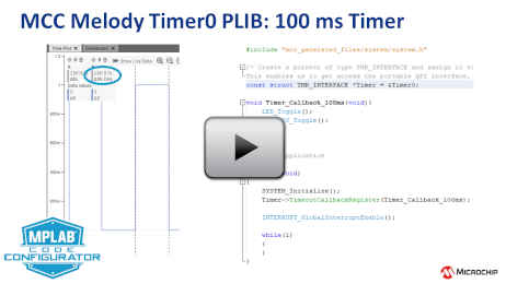
This use-case configures Timer0 (TMR0) in 8-bit mode to generate an overflow interrupt at a period of 100ms, toggling a LED at this period.
-
Timer > Hardware Settings:
-
Clock Source set to LFINTOSC //Low Frequency Internal Oscillator
-
Clock Prescaler 1:16
-
Requested Period(s): 0.1(s).
-
-
Timer > Interrupt Settings:
-
TMR Interrupt: Yes.
-
-
System > Pins (for all pins check board schematics):
-
Pin Grid View: Select LED pin, DebugIO pin as outputs (Check board schematic).
-
Pins: Rename Custom Names to "LED" and "DebugIO", respectively.
-
#include "mcc_generated_files/system/system.h"

/* Create a pointer of type TMR_INTERFACE and assign it to the address of the Timer0 TMR_INTERFACE struct.
This enables us to get access the portable API interface, which ensures that it's easy to change the peripheral instance the timer runs on. */
const struct TMR_INTERFACE *Timer = &Timer0;
void Timer_Callback_100ms(void){
    LED_Toggle();
    DebugIO_Toggle();
}
int main(void)
{
    SYSTEM_Initialize();
    Timer->TimeoutCallbackRegister(Timer_Callback_100ms);

    INTERRUPT_GlobalInterruptEnable();

    while(1){}
}
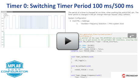
Timer Use Case 2: Timer Switch Frequency 100 ms / 500 ms
This use case toggles the time-out period between 100 ms and 500 ms, when the switch is pressed.
-
Timer > Hardware Settings:
-
Clock Source set to LFINTOSC //Low Frequency Internal Oscillator
-
Clock Prescaler 1:1 //Default
-
Timer Mode: 16-bit
-
Requested Period(s): 0.1(s).
-
-
Timer > Interrupt Settings:
-
TMR Interrupt: Yes.
-
-
System > Pins (for all pins check board schematics):
-
Pin Grid View: Select LED pin as output
-
Pins: Rename Custom Name to "LED".
-
SWITCH pin as INPUT, name it "SW".
-
Enable Weak Pullup if needed
-
Interrupt on Change: Sense negative/positive on switch press
-
#include "mcc_generated_files/system/system.h"

/* Create a pointer of type TMR_INTERFACE and assign it to the address of the Timer0 TMR_INTERFACE struct.
This enables us to get access the portable API interface, which ensures that it's easy to change the peripheral instance the timer runs on. */
const struct TMR_INTERFACE *Timer = &Timer0;

#define LED_100ms (0xF3E4)
#define LED_500ms (0xC374)
volatile bool CHANGE_PERIOD = false;
volatile bool PERIOD_100ms = true;  /*Global variable to check the current period value*/
void Timer_Callback(void)
{
    LED_Toggle();
}

void SW_Callback(void)
{
    CHANGE_PERIOD = true;
}

void Timer_Change_Frequency(void){
    Timer->Stop();
    if(PERIOD_100ms)
    {
        TMR0 = 0x0;   //Restart the timer
        Timer->PeriodCountSet(LED_500ms);
        PERIOD_100ms = false;
    }
    else
    {
        TMR0 = 0x0;   //Restart the timer
        Timer->PeriodCountSet(LED_100ms);
        PERIOD_100ms = true;
    }
    Timer->Start();
}
int main(void)
{
    SYSTEM_Initialize();
    Timer->TimeoutCallbackRegister(Timer_Callback);
    RC0_SetInterruptHandler(SW_Callback);             /* Select for SW pin you are using */

    INTERRUPT_GlobalInterruptEnable();

    while(1)
    {
        if(CHANGE_PERIOD)
        {
            Timer_Change_Frequency();
            __delay_ms(100);    //De-bounce delay
            CHANGE_PERIOD = false;
        }
    }
}
Timer Use Case 3: Timer Wake From Sleep Every 10s
How to configure and operate TMR0 in 16-bit mode, wake the microcontroller from sleep mode, every ten seconds. The wake up interrupt callback blinks a LED for ON for 100 ms, then puts the MCU back to Sleep.
-
Timer > Hardware Settings:
-
Clock Prescaler: 1:32 (or greater)
-
Timer Mode: 16-bit
-
Clock Source set to LFINTOSC //Low Frequency Internal Oscillator
-
Requested Period(s): 10 seconds
-
-
Timer > Interrupt Settings:
-
TMR Interrupt: Yes. //No callback, only used to wake MCU from sleep.
-
-
System > Pins (for all pins check board schematics):
-
Pin Grid View: Select LED pin, DebugIO pins as outputs.
-
Pins: Rename Custom Names to "LED" and "DebugIO", respectively.
-
#include "mcc_generated_files/system/system.h"
int main(void)
{
    SYSTEM_Initialize();

    // Enable the Global Interrupts
    INTERRUPT_GlobalInterruptEnable();

    while(1){
        LED_SetLow();     //Set LED High
        DebugIO_SetLow();
        __delay_ms(100);  //100ms Delay in between LED toggle
        LED_SetHigh();    //Set LED Low
        DebugIO_SetHigh();
        SLEEP();          //Put microcontroller in Sleep
    }
}
Timer Use Case 4: 125 kHz Output Signal on GPIO
A 125 Hz signal will be generated on the GPIO pin using the Peripheral Pin Select (PPS).
-
Timer > Hardware Settings:
-
Clock Source set to LFINTOSC. //Low Frequency Internal Oscillator
-
Set Requested Period(s) to 0.004 seconds.
-
-
System > Pins (for all pins check board schematics):
-
Pin Grid View > TMR0 Output: Select GPIO to use as CLK_OUT pin
-
#include "mcc_generated_files/system/system.h"
int main(void)
{
    SYSTEM_Initialize();

    while(1){}
}