5 Buttons and LEDs

Digital Addressable LEDs, RGB LED, LED Row, Joystick, Tactile- and Touch Buttons, CNANO Reset Button.

Digital Addressable LEDsRGB LEDLED Row and I/O Expander 1Buttons, Joystick and I/O Expander 2Touch ControllerStandalone Touch ButtonCNANO Reset Button

5.1 Digital Addressable LEDs

The Explorer features eight serially addressable RGB LEDs. These LEDs behave similarly to WS2812B LEDs. Comparator U301 (MCP6561) connects the control signal from the CNANO socket and acts as a logic-level translator.
  • Select the power source using the J316 pin header
  • Supply external power through the J302 pin header
  • The LED strip is extendable using the J303 pin header
Tip: The LED strip input is available through the pin header footprint J313.
Figure 5-1. Addressable LED Circuit
Remapping AreaBoard Overview
Important: Long LED strips consume a lot of current, and it is recommended to use an external supply to power LED strips attached to the board.
Tip: Check out the PIC® and AVR® examples for driving WS2812 or similar LEDs on MPLAB® Discover.

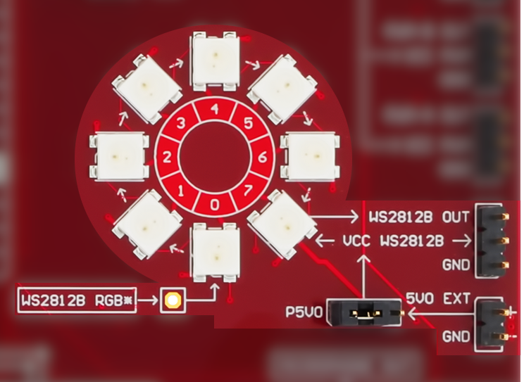
Related information: Addressable LEDs Timing and Format.

5.2 RGB LED

An RGB LED is connected to the PWM outputs from the CNANO socket.
CAUTION: The LED is very bright when driven at full power – do not stare at it.
The PWM outputs from the CNANO socket are shared between the servomotor driver and the mikroBUS socket. Disconnect the different channels by removing the jumper caps from J203 and J309.
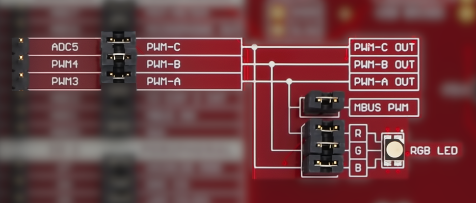
  • Pin header J309 connects the RGB LED to the CNANO socket
  • Pin header J203 connects the mikroBUS PWM channel to the CNANO socket
Figure 5-2. RGB LED Overview
Board OverviewRemapping AreaMBUSServo-Motor Headers
Tip: Check out the PIC and AVR examples for driving RGB LEDs on MPLAB® Discover.

5.3 LED Row and I/O Expander 1

LED Row

The Explorer features eight controllable yellow LEDs. Turn the LED on by pulling the pin low (active-low).

The eight LEDs can be controlled in three different ways:
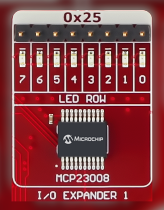
  1. From the Remapping Area.
  2. From I/O Expander 1 via the I2C Bus.
  3. From the 1x8 pin header (J301).

I/O Expander 1

Set the GP pin to output-low mode on the I/O Expander to activate (turn on) the LED.
Info: Each LED is connected to a resistor network, ensuring that no short circuits occur if controlled from multiple sides simultaneously.
Figure 5-3. LED Row Connections
Board OverviewRemapping AreaI2C Bus
Info: I/O Expander 1’s 7-bit I2C address: 0x25. The I2C address can be changed using pins A0-A2 and follows the address format ‘0100, A2, A1, A0’.

5.4 Buttons, Joystick and I/O Expander 2

Tactile and Touch Buttons

Three tactile and three touch buttons are available as user inputs on the Explorer. The buttons are connected in a group of one LED, one tactile, and one touch button. The grouping is shown on the silkscreen. Pressing any button in the same group will assert the same signal and activate the LED.

The button signals can be accessed in three different ways:
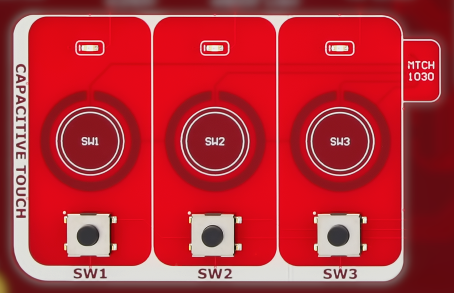
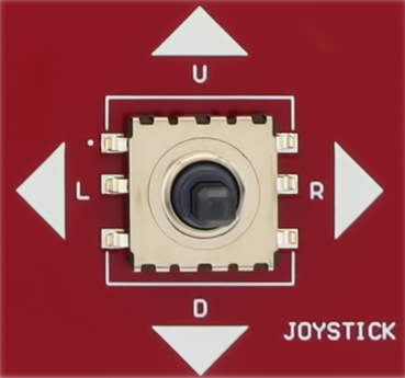
  1. From the Remapping Area.
  2. From I/O Expander 2 via the I2C Bus.
  3. From the 1x8 pin header (J401).
Tip: See section Touch Controller for more information on the touch buttons.

Joystick

The joystick signals can be accessed in two different ways:
  1. From I/O Expander 2 via the I2C Bus.
  2. From the 1x8 pin header (J401).

I/O Expander 2

Configure the GP pins as inputs with internal pull-ups to read the button states with the I/O Expander.
Info: Each button signal is connected to a resistor network, ensuring there are no short circuit occurs if a pin is set high while the button is pressed.
Figure 5-4. Buttons and Joystick Connections
I2C BusTactile and Touch Button CircuitRemapping AreaBoard Overview
Info: I/O Expander 2’s 7-bit I2C address: 0x24. The I2C address can be changed using pins A0-A2 and follows the address format ‘0100, A2, A1, A0’.

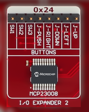
5.5 Touch Controller

The three touch buttons are connected to the MTCH1030 touch controller. The touch buttons are sensed using capacitive touch sensors with active shields utilizing the Driven Shield Plus feature.

Response time, oversampling, touch sensistivity, easy tune, and single-button mode are configured through resistors networks on the bottom side of the Explorer. The parameters are read by the touch controller during power-up and only the single-button mode can be altered at run-time.
Info: OUTx pin indicates the touch detection state of BUTTONx. The pin idles in a high-impedance state. When the touch button is pressed, it switches to output-low.
Figure 5-5. MTCH1030 Connections
I/O Expander 2Board Overview
Info: By default, the Touch Tune Data feature of MTCH1030 is disabled due to the pull-up resistor on pin OUT1. To use this feature, refer to the chapter MTCH1030 Touch Tune Data in the appendix.
Info: The MTCH1030 enables anti-touch recalibration if a touch button pressed for more than 8s. This causes the OUTx pin to revert to a high-impedance state.
The MTCH1030 touch controller on the Explorer is configured as follows:
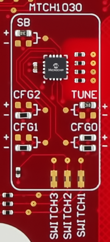
  • Measurement Period: Back-to-back measurements (minimum period)
  • Oversampling: Eight samples per measurement cycle
  • Sensitivity: 0-63
  • Easy Tune: Disabled
  • Single-Button Mode: Disabled
Tip: Touch sensor data captured with MTCH1030 can be visualized using the MPLAB® Data Visualizer, see section MTCH1030 Touch Tune Data.

5.6 Standalone Touch Button

Underneath the Microchip logo is a single standalone capacitive touch button with an optional active shield.

If the microcontroller on the CNANO supports capacitive touch sensing, the standalone capacitive touch button can be used by connecting it to the remapping area from the 1x2 pin header J404. See section Direct Remapping.

The sensor and shield pins are labeled in the silkscreen next to the pin header.
Figure 5-6. Standalone Touch Button
Board Overview
Tip: Generate code with the capacitive touch library in MCC Melody and visualize touch sensor data in MPLAB® Data Visualizer.

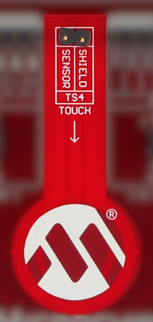
5.7 CNANO Reset Button
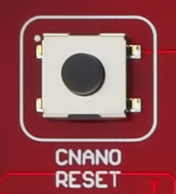
The Explorer features a reset button connected to the default reset pin location of the CNANO. The CNANO microcontroller (MCU) must have the reset functionality enabled for this button to work. Refer to your MCU’s data sheet to determine the pin location and function, and consult the CNANO schematics to see how it is connected.
Important: The reset button will reset only the CNANO MCU. Pressing the button will not reset the peripherals on the Explorer.
Figure 5-7. CNANO Reset Button
Board Overview