6 Serial Communication

USB Bridge, UART, I2C and SPI Peripherals.

USB BridgeUART PeripheralsI2C PeripheralsSPI Peripherals

6.1 USB Bridge

The MCP2221A is a USB-to-UART/I2C serial converter. It bridges the gap between a computer's USB port and the I2C and UART interfaces on the Explorer.

When the on-board USB-C® is disconnected, the USB bridge is held in reset. You can keep the USB bridge in reset using the MCU on the CNANO by pulling IO-37 on the Explorer low.
Tip: When not in use, it is recommended to disconnect the bridge reset from the CNANO socket by removing the jumper cap on IO-37.
Figure 6-1. USB Bridge Overview
Board OverviewRemapping AreaI2C BusUARTPower Mux
Tip: Drivers, CLI tools and apps are available to interface with the MCP2221A on its web page.
The USB bridge can be disconnected from the main I2C bus on the Explorer using slide switch S500. When disconnected, the USB bridge and the power monitor IC are isolated on their own I2C bus.
Important: The USB bridge is only able to act as an I2C host.

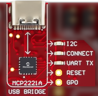
The UART connection to the CNANO socket is shared between the USB bridge and the mikroBUS socket. Use slide switch S501 to select the connected UART.

6.2 UART Peripherals

The CNANO’s default UART pins are shared between the USB bridge and the mikroBUS socket. Only one of the connections is active at any time. Select which pins are connected to the CNANO socket using slide switch S501.
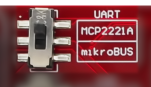
Figure 6-2. UART Overview
Board OverviewRemapping AreaMBUSUSB BridgeUSB Bridge

6.3 I2C Peripherals

6.3.1 I2C Bus

Figure 6-3. I2C Bus Overview
Board OverviewRemapping AreaGroveQwiicMBUSTemperature SensorSecure ElementProximity and Ambient Light SensorI2C EEPROMI/O Expander 1I/O Expander 2OLED ScreenPower MonitorUSB Bridge

The Explorer features an I2C bus with several attached devices and external connectivity options. All connected devices are compatible with Standard Mode (100 kHz) and Fast Mode (400 kHz) I2C. The bus is designed to meet the rise-time requirements for both modes. The SDA and SCL signals are connected to the COM section of the CNANO socket.

Important: Connecting I2C extension boards with pull-ups will impact bus performance.

The Explorer’s I2C bus can be split into two separate buses using the slide switch S500. Each bus has its own set of pull-ups - I2C pull-ups A and B.

When the I2C bus is split, the USB bridge and the power monitor ICs are isolated from the main I2C bus, with the USB bridge acting as the host to communicate with the power monitor IC.
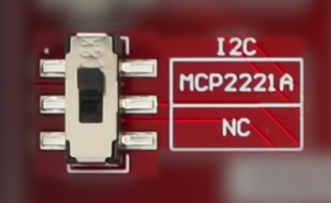
Important: The USB bridge can function only as an I2C host.
Table 6-1. I2C Electrical Characteristics
ParameterValue
I2C Pull-up A2.7 kΩ
I2C Pull-up B5.1 kΩ
I2C bus with Pull-ups A and B
I2C bus capacitance1130 pF
Rise-time2~200 ns
I2C bus with Pull-up A isolated
I2C bus capacitance195 pF
Rise-time2~220 ns
I2C bus with Pull-up B isolated
I2C bus capacitance135 pF
Rise-time2~150 ns
Note:

1Bus capacitance calculated using measured rise time with equation 1 from the I2C-bus specification and user manual.

2Rise time is defined as the time it takes for the I2C bus to rise from 0.3*VDD to 0.7*VDD.

6.3.2 Temperature Sensor

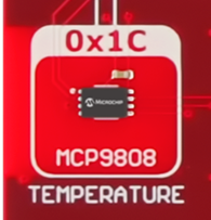
MCP9808 is a digital temperature sensor connected to the Explorer’s I2C bus. The alert pin is connected to the CNANO socket IO-24.
  • Accuracy:
    • ±0.25°C (typical) from -40°C to +125°C
    • ±0.5°C (maximum) from -20°C to +100°C
  • User selectable measurement resolution:
    • 0.0625°C
    • 0.125°C
    • 0.25°C
    • 0.5°C
  • User programmable temperature limits:
    • Temperature window limit
    • Critical temperature limit
Info: 7-bit I2C address: 0x1C. The I2C address can be changed using pins A0-A2 and follows the address format ‘0011, A2, A1, A0’.
Figure 6-4. Temperature Sensor
Remapping AreaI2C BusBoard Overview

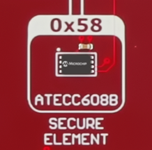
6.3.3 Secure Element

ATECC608B is a secure element in the Microchip CryptoAuthentication family and is connected to the Explorer’s I2C bus.
  • Supports advanced Elliptic Curve Cryptography (ECC)
  • Protected storage for up to 16 keys, certificates or data
  • Internal random number generator
  • Secure boot support
Info: 7-bit I2C address: 0x58.
Figure 6-5. Secure Element
I2C BusBoard OverviewRemapping Area
Info: The ATECC608B-MAH4I used on the Explorer is pre-provisioned for the Microchip Trust Platform and configured to support some of the most common IoT use cases. For more details, visit: https://www.microchip.com/en-us/products/security/trust-platform/trustflex.

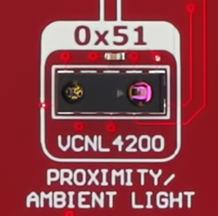
6.3.4 Proximity and Ambient Light Sensor

VCNL4200 is a proximity sensor (PS) and ambient light sensor (ALS) connected to the Explorer’s I2C bus.
  • Programmable emitter current
  • 16-bit resolution ALS
  • 12-bit/16-bit resolution PS
  • Detection distance of up to 1.5m
  • Interrupt function available for ALS and PS with upper and lower thresholds
Info: 7-bit I2C address: 0x51.
Figure 6-6. Proximity and Ambient Light Sensor
Remapping AreaBoard OverviewI2C Bus

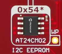
6.3.5 2 Mb Serial EEPROM

AT24CM02 is a 2 Mb Serial EEPROM connected to the Explorer’s I2C bus.

  • 1024 pages of 256 bytes each
  • Random, byte and sequential read modes
  • Byte and page write modes
  • Built in error detection and correction
  • Hardware write protection
Info: 7-bit I2C address space: 0x54 - 0x57.
Figure 6-7. I2C EEPROM
Board OverviewRemapping AreaI2C Bus
Info: The write protect pin is available through pin header footprint J209 and can be remapped to the CNANO socket.

6.3.6 I/O Expanders

The Explorer features two MCP23008 I/O expanders connected to the I2C bus.

  • 8-bit bidirectional I/O port
  • I/O pins default to input
  • Configurable interrupt output pin
I/O Expander 1 is set up to control the LED row containing eight yellow LEDs.
I/O Expander 2 is set up to read the status of the joystick and tactile or touch buttons.

6.3.7 OLED Display Module

The Explorer features an OLED display connected to the I2C bus.
  • SSD1306 display driver
  • 1.30” screen size with 128x64 pixel resolution
  • Fast response time (≦ 10 µs)
  • Typical brightness: 120 cd/m2
Info: 7-bit I2C address: 0x3D. Alternative I2C address 0x3C can be used by connecting pin A0 to GND.
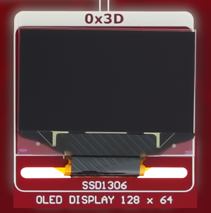
Figure 6-8. OLED Display
I2C BusBoard OverviewRemapping Area

6.4 SPI Peripherals

6.4.1 SPI Bus

The Explorer features an SPI bus with several peripherals and a MikroBus socket attached. The individual Chip Select (CS) pins and the mutual SPI bus pins are routed to the CNANO socket.
Figure 6-9. SPI Bus Overview
Board OverviewRemapping AreaSPI EEPROMDACMicroSD Card SocketMBUS
Info: A 47 kΩ pull-up resistor (R221) is mounted on the MISO line close to the microSD card socket, causing the MISO line to idle high.

6.4.2 Digital-to-Analog Converter

MCP4821 is a single-channel 12-bit Digital-to-Analog converter (DAC) with internal voltage reference. The DAC is connected to the SPI bus on the Explorer.
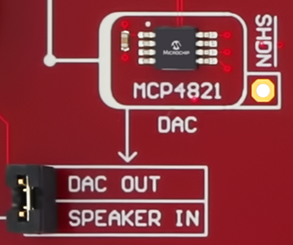
  • SPI with 20 MHz clock support
  • 2.048V Internal voltage reference (Vref)
  • DAC output, limited by supply voltage (3.3V)
  • Synchronous update of DAC output using the LDAC pin
Table 6-2. Programmable Gain
Gain SelectionIdeal Output RangeLSb Size
2.048V0.0-2.0475V0.5 mV
4.096V0.0-3.299V1.0 mV
Figure 6-10. DAC Overview
Board OverviewRemapping AreaSPI BusSpeaker Circuit
Tip: The DAC output is connected to the speaker circuit by default. It can be remapped using pin header J202.

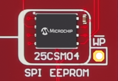
6.4.3 4 Mb Serial EEPROM

25CSM04 is a 4 Mb Serial EEPROM connected to the Explorer’s SPI bus.

  • SPI with up to 8 MHz clock support
  • 2048 pages of 256 bytes each
  • Byte or sequential reads
  • Byte or page writes
  • Built-in Error Correction Code (ECC)
  • Configurable software and/or hardware write protection
Figure 6-11. SPI EEPROM
Board OverviewRemapping AreaSPI Bus
Tip: Enable the hardware write-protected feature by pulling the WP pin low.

6.4.4 microSD Card Socket

The Explorer features a microSD card socket connected to its SPI bus. Only pins required for an SPI connection to a microSD card are connected to the CNANO socket.

All pins of the microSD card socket are available on pin headers close to the microSD card socket. The pin headers allow devices with a dedicated high-speed multimedia interface to fully utilize all data lines of a connected microSD card.
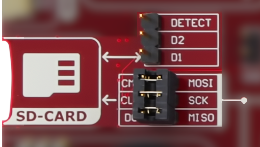
Tip: D1, D2, and the card detect pins are routed to a separate pin header (J212). With no card inserted, the card-detect pin is low.
Figure 6-12. microSD Card
SPI BusBoard OverviewRemapping Area
Info: A 47 kΩ pull-up resistor (R221) is mounted on the MISO line close to the microSD card socket, causing the MISO line to idle high.