
4 Power Supply and Monitor
Power supply, Power Monitor.

4.1 Power Supply

- Dedicated 3.3V regulator to power
the CNANO and 3.3V peripherals
- The CNANO’s target regulator is disabled while connected to the Explorer
- 5V peripherals powered directly by USB voltage
- A power multiplexer allows power supplied from the on-board USB-C® connector or the CNANO
- A current limiting switch with a soft start to protect the board, the current limit set at 2A
- On-board power monitoring for voltage and current measurement with four channels
| Power Domain | Vnom | Vmin - Vmax | Imax |
|---|---|---|---|
| P5V0 | 5.0V | 4.4–5.5V | 2.0A |
| P3V3 | 3.30V | 3.22–3.38V | 1.2A |
| CNANO P3V3 | 3.30V | 3.22–3.38V | 1.2A |
| BRIDGE P3V3 | 3.30V | 3.23–3.37V | 150 mA |
4.1.1 Power Sources
- The USB connector on the CNANO
- The USB-C® connector on the Explorer
- The CNANO’s VBUS output has a current limitation of 500 mA
- The Explorer’s USB-C® connector can sink different amounts of current based on the USB source (up to 3.0A from a USB-C® source)
- Both USB inputs are fed into a power multiplexer, with output current limited to 2.0A

4.1.2 Power Domains
There are four main power domains on the Explorer:
|  |
CNANO P3V3 is powered by the same regulator as P3V3, separated for dedicated power measurement of the CNANO. It powers the CNANO’s external power input. Refer to CNANO Power Configuration for more information.
| Power Domain | Power Measurement Channel | Peripheral |
|---|---|---|
| CNANO P3V3 | CH1 (uA), CH4 (mA) | Connected CNANO |
| P3V3 | CH2 (mA) | Touch controller |
| I/O expander 2 + button LEDs | ||
| I/O expander 1 + LED row | ||
| I2C EEPROM | ||
| Secure Element | ||
| Proximity and ambient light sensor (digital circuitry) | ||
| Temperature sensor | ||
| OLED display | ||
| SPI EEPROM | ||
| DAC | ||
| Voltage reference | ||
| Microphone circuit | ||
| Speaker circuit | ||
| Potentiometer | ||
| mikroBUS™ socket (3.3V pin) | ||
| MicroSD card socket | ||
| Grove and Qwiic®connector | ||
| P5V0 | CH3 (mA) | RGB LED |
| Digital addressable LEDs | ||
| Servomotor circuit | ||
| Proximity and ambient light sensor (internal LED) | ||
| mikroBUS™ socket (5V pin) | ||
| BRIDGE P3V3 | - | Power monitor circuit |
| USB bridge circuit |

4.1.3 Current Limiting Switch

4.1.4 CNANO Power Configuration
The Explorer supplies the CNANO with a fixed 3.3V. When connected to the Explorer, the on-board regulator of the CNANO is disabled by pulling the VOFF pin low, ensuring no logic level mismatches between the CNANO and the Explorer.

4.2 Power Monitor
4.2.1 Getting Started with Power Monitor
The on-board PAC1944 quad-channel power monitor circuit allows tracking of the power consumption of peripherals on the Explorer. The measurement data can be accessed through the USB bridge MCP2221A.
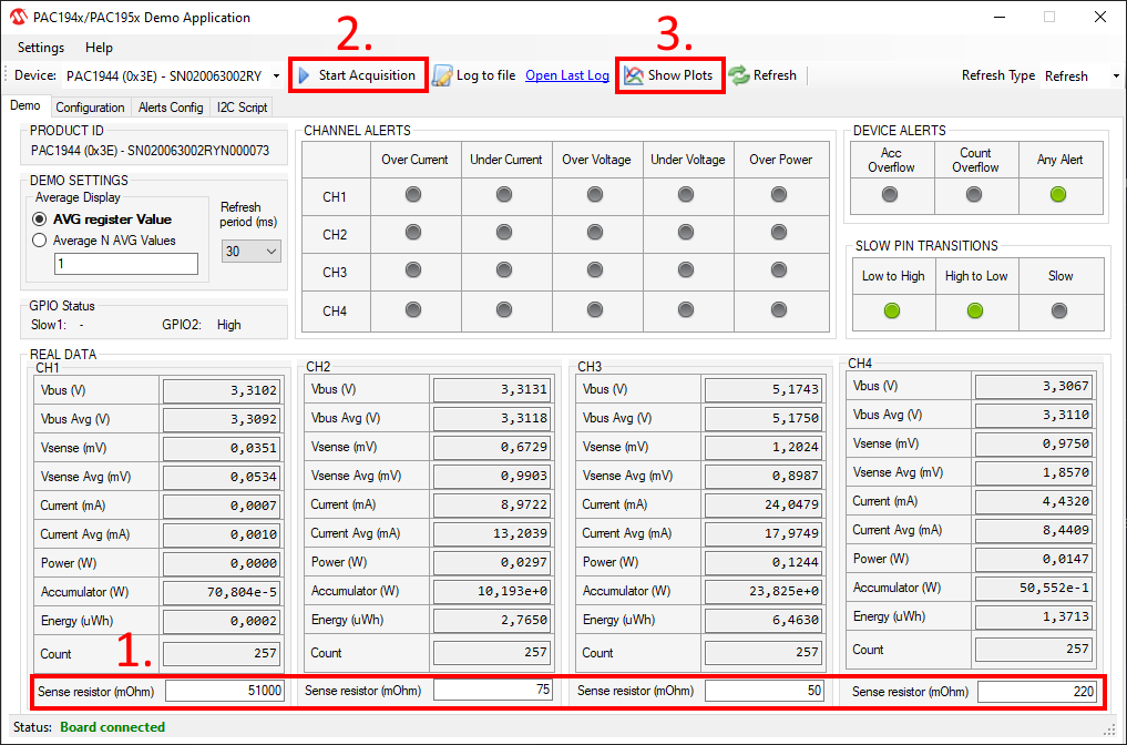
- Configure the sense resistor value:
- Channel 1: 51000
- Channel 2: 75
- Channel 3: 50
- Channel 4: 220
- Start Acquisition.
- Press "Show Plots" to visualize the data.
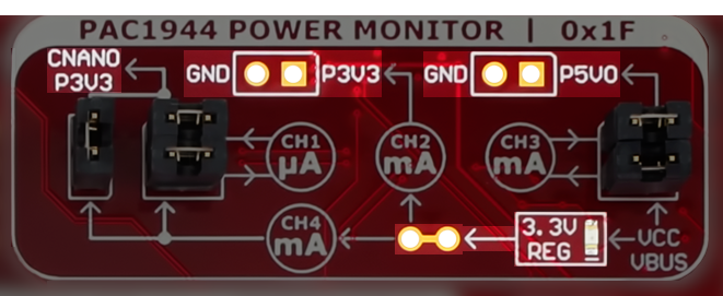
4.2.2 Power Measurement Channels
The four PAC1944 measurement channels measure three of the four main power domains on the Explorer:
|  |

| Default Power Domain | Channel | Current Sense Range | Current Sense Resolution | Sense Resistor |
|---|---|---|---|---|
| P5V0 (mA) | CH3 | ≤ 2.00A | 30.5 μA | 0.050Ω |
| P3V3 (mA) | CH2 | ≤ 1.33A | 20.3 μA | 0.075Ω |
| CNANO P3V3 (mA) | CH4 | ≤ 455 mA | 6.94 μA | 0.220Ω |
| CNANO P3V3 (μA) | CH1 | ≤ 1.96 mA | 29.9 nA | 51.0Ω |
Measure CNANO P3V3 Power
- CH1 for µA measurements
- CH4 for mA measurements
 |  |
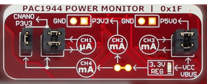
Measure External Power
CH1 and CH3 can be disconnected from their default connections to measure current from external sources.
 |  |
4.2.3 Quad Channel Precision Power Monitor
Feature overview:
The PAC1944 may also be accessed by the microcontroller on the CNANO using the I2C bus. | 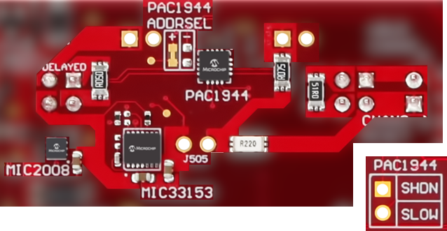 |
