
1.3.4 Bootloader:Bootloader Interrupt Selection
- AIVT Interrupts
-
The operation of the interrupts in the bootloader depends on the type of the device. If using a device with a non-relocatable AIVT table like the PIC24FJ128GA204 that is on this board, the software will use both the IVT and IAVT. MCC will configure the device code to forward all interrupts while in bootloader mode to the Alternate Interrupt Vector Table. Then when in the Application mode all interrupts will be forwarded to the Interrupt Vector table. This is described in detail in the MCC Help section, Interrupt Handling. For devices with this type of interrupts, the user does not need to do anything special for the bootloader code and nothing extra will show up on the application.
- IVT Interrupts
-
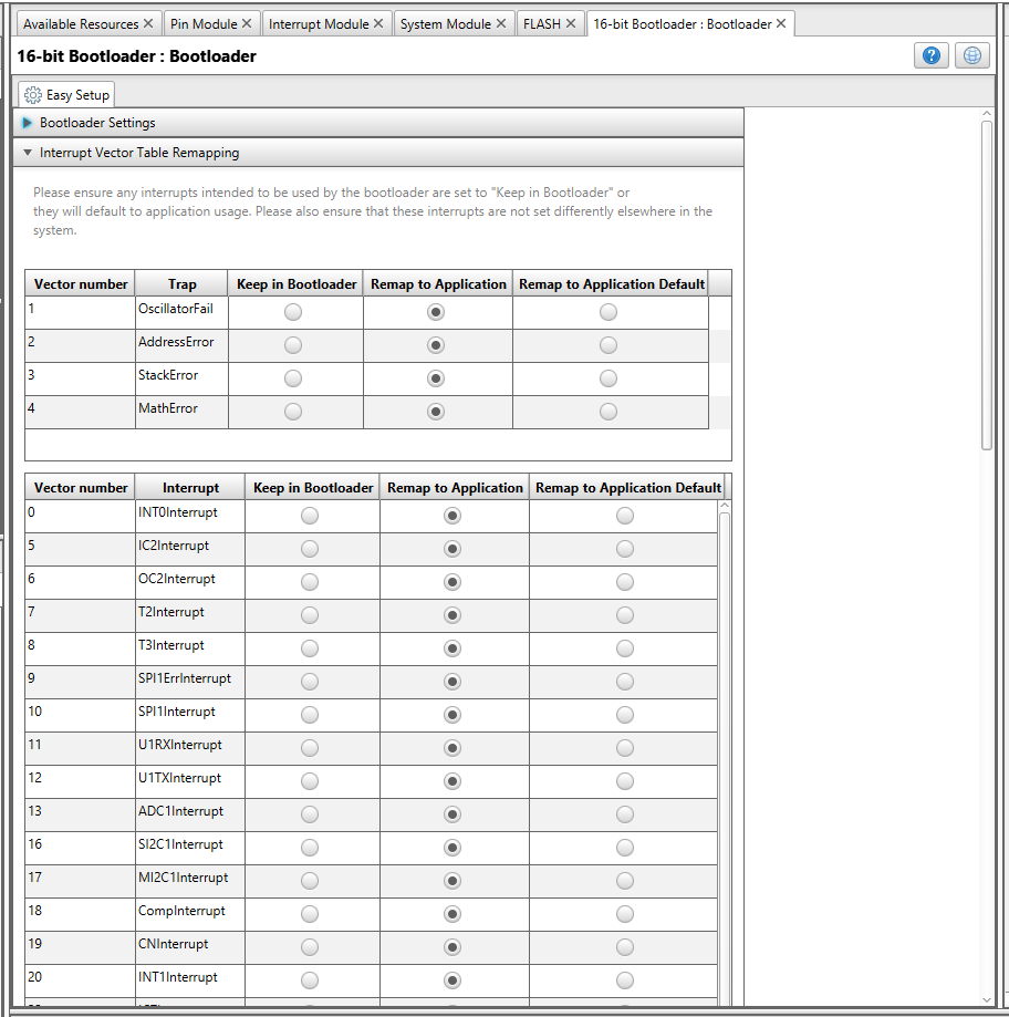
On many parts the AIVT table is relocatable and is usable only if Code Guard is enabled. In order to limit the complexity, Code Guard will not be enabled, and hence just the IVT will be used for both bootloader and application interrupts as described in 16-bit Bootloader::Bootloader->Interrupt Handling. For these parts, there is an extra table below the Bootloader Settings, shown below, allowing the user to select whether each interrupt/trap should be handled by the bootloader or the application. If the user selects Remap to Application, the interrupt will be forwarded to application. If the user has a specific ISR written, the linker will automatically link this call to that ISR. However, if no application ISR is available, the interrupt will be handled by the application default ISR. If the user needs to further reduce memory space, they can force un-used interrupts to "Remap to Application Default". This will save flash space in the application area since the FW will not need a unique interrupt entry for each interrupt in the user interrupt table which is described in 16-bit Bootloader::Bootloader->Interrupt Handling.
The project can now be built. Since a blinking LED was desired while the bootloader was running, a simple LED blink routine called updateLeds() needs to be added to the function RunBootLoader() in boot_demo.c shown below. This assumes a pin has been created with this name. This was done above.
#include "../pin_manager.h"

void updateLeds()
{
    #define LED_RATE 0x8000
    static int count=0;

    count++;
    if ((count % LED_RATE)==0)
    {
        LED1_SetLow();
        if ((count/LED_RATE) & 1)
        LED1_SetHigh();
    }
}
To enable the Run Boot Loader Switch, add the line return (RUN_BL_SW_GetValue()==0); to the function bool EnterBootLoadMode(void) in the file boot_demo.c. This assumes that a pin has been defined as an input with the name RUN_BL_SW. This was done above.
bool EnterBootLoadMode(void)
{
    / * Replace with your own logic here for when to stay in boot load mode. * /
    / * return false; * /
    return (RUN_BL_SW_GetValue()==0);
}
At this point, this code will be blinking LED1 and will be waiting for a connection to the unified host controller referenced above. The next step is to generate the application code.