
2.13 MCLV 48V 300W Development Board Setup for Sensorless Mode PIC32MK MCM
Setting Up the Hardware
The following table shows the target hardware for the application projects
| Project Name | Description |
|---|---|
| mclv_48v_pic32mk_mcm_dim.X |
Setting Up MCLV 48V 300W Development Board
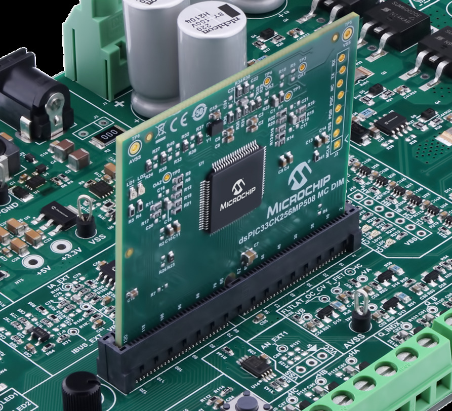
- Insert the PIC32MK MCM Motor
Control Dual In-Line Module on J8 interface header.
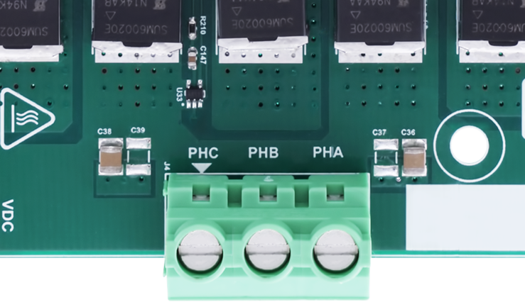
- Motor Connections: Connect
the 3 Phase connections of the motor on the J4 header
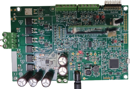
- Power the board with a 24V DC supply using J1 or J3(+,-) header. For
additional safety, it is recommended to use a current limited power supply
while testing this software demonstration on a non-default hardware and
motor.

- Complete Setup
Running the Application
- Build and Program the application using its IDE
- Press switch SW1 to start the motor
- Vary potentiometer to change the speed of the motor
- Press switch SW1 to stop the motor
- Press switch SW2 to change the direction of the motor
- Press switch SW1 again to start the motor
- Monitor graphs on X2C Scope
Refer to the following tables for switch and LED details:
| Switch | Description |
|---|---|
| Switch SW1 | To start or stop the motor. |
| Switch SW2 | To change the direction of
rotation. Direction toggle command is accepted only when motor is stationary. |
| LED D3 Status | Description |
|---|---|
| OFF | Motor spin direction is “positive”. |
| ON | Motor spin direction is “negative”. |
| LED D4 Status | Description |
|---|---|
| OFF | No fault. |
| ON | Fault is detected. |