
3 MCC Melody GUI
This document provides information about the MCC Melody Core details instructions on using its features like the Toolbar, Easy View and Register Initialization/View.
3.1 Introduction
MPLAB® Code Configurator (MCC) Melody Core provides Libraries, Drivers, and Peripheral Libraries (PLIB) for the development of embedded software for Microchip PIC® and AVR® Microcontrollers (MCUs) and dsPIC® Digital Signal Controllers (DSCs). The MCC Melody Components are customized via a graphical configuration tool, which generates highly efficient C code.
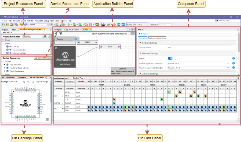
Resource Management Panel: The Resource Management Area has two views: The tree and the flat view. Both provide access to the complete list of software/peripheral components and the selected components for the current project configuration.
Application Builder Panel: A structured relationship manager with used resources, providing a clear visualization of a component's related dependencies and context in your project.
Composer Panel: When a peripheral, library or other external component is selected from the Project Resources Area, its corresponding configuration GUI is displayed in the Composer Area.
Pins Package Panel: Displays pins in graphical view and provides a zooming feature by the scrolling mouse wheel when the mouse is over the package view.
Pin Grid Panel: Displays pins in a structured table format,with lock and unlock features.
3.2 Melody Component Toolbar
The Toolbar provides quick access to commonly used functionality of Easy Views and Register views, such as Search , Text Size , Expand/Collapse and Track Change.
The toolbar is available for all Easy Views and Register Views.
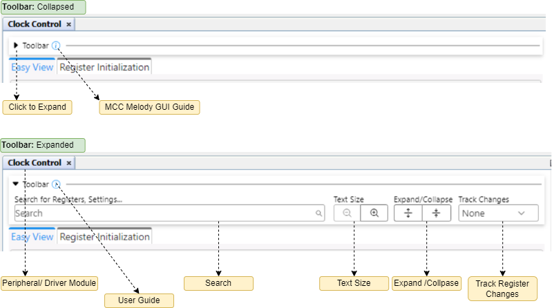
3.2.1 Search
This feature allows users to quickly find specific information within the views.
Users can search across register names, settings names, descriptions, values and more in both Easy view and Register view.
- Easy View
- Register Initialization/ Register View.
- Register names.
- Settings names.
- Descriptions
- Bit values
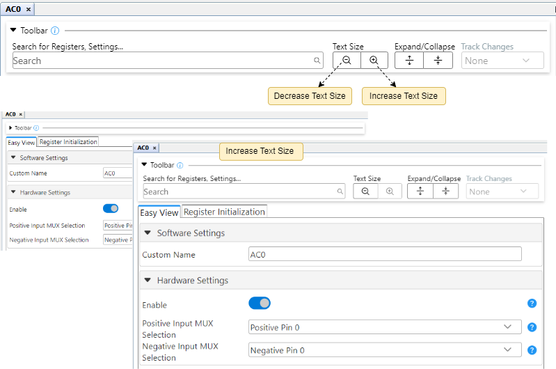
3.2.2 Text Size
Adjust text size using two buttons located inside the toolbar.
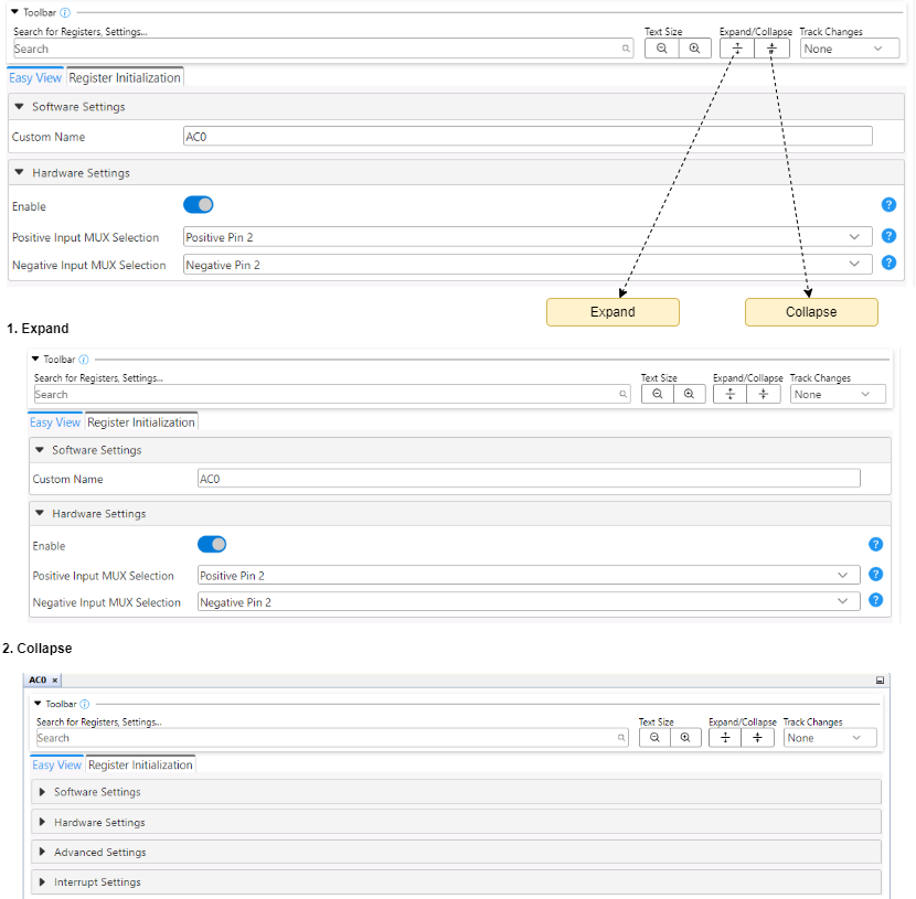
3.2.3 Expand/Collapse
This feature allows users to quickly show or hide the content within the groups.
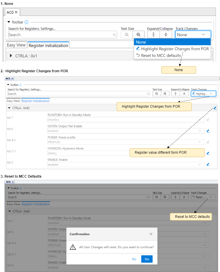
3.2.4 Track Changes
The Track Changes feature is enabled for Register Initialization/ Register View only (not enabled for Easy View) supporting tracking of Registers/Settings values concerning POR (Power-on Reset) values.
| # | Option | Description | On Selection |
|---|---|---|---|
| 1 | None | No register values are tracked.[Default selected] | No Action |
| 2 | Highlight Register Changes from POR | POR: Highlight default Register values as mentioned in the datasheet. | Enables highlighted and downlighted icons beside each Register/Settings to represent changes only |
| 3 | Reset to MCC Defaults | Resets the user-modified values to default MCC values |
|
3.3 Pins
Configures the pins for the device.
This feature allows users to configure the pins of the device. It has three views, listed below, that represent all pins in a graphical user interface.
- Pin Easy View
- Pin Grid View
- Pin Package View
3.3.1 Pin Easy View
For any pin which has been configured in the Pin Grid View, additional configuration of that pin can be done using the Pin Easy View. To display the Pin Easy View, click on the Pins tab in the Project Resources Area.
The following settings are available in this view (depending on the selected pin).
| Sl. No | Column Name | Description |
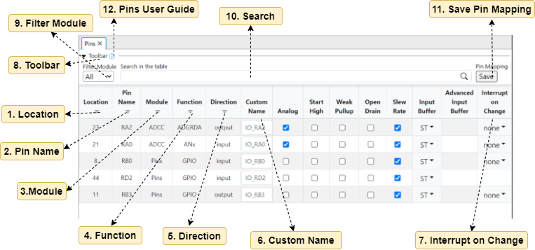
| 1 | Location | It refers to the physical pin number on the device package and the corresponding port pin designation. |
| 2 | Pin Name | The port pin name. |
| 3 | Module | The name of the module containing the function of the pin. |
| 4 | Function | Module-specific functionality available on the pin. A pin may have one or more selectable functions. Typically, a pin may be configured to have several functions at the same time if it s also configured as an input (Output column unchecked). Only one function per each pin can be matched with an output direction. Refer to the device data sheet for more details. |
| 5 | Direction | Shows the pin direction of the pin (i.e. bidirectional). |
| 6 | Custom Name | It is the prefix used in API names. A set of macros [#define API] are generated with custom name for e.g. RA1_Toggle, LED_Toggle. |
| 7 | Interrupt on Change | Configures the interrupt-on-change capability of the pin. |
| 8 | Toolbar | The Toolbar provides quick access to commonly used functionality. |
| 9 | Filter Module | This feature displays the filtered module with a highlighted color. |
| 10 | Search | This feature allows users to quickly find specific information. |
| 11 | Save Pin Mapping | This feature allows users to save pin mappings in csv format. |
| 12 | Pins User Guide | Redirects to the user guide that outlines the usage and features of the pins. |
3.3.1.1 Filter Module
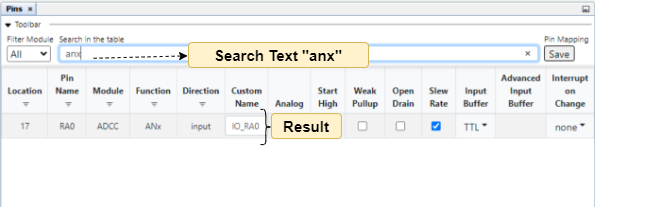
3.3.1.2 Search
This feature allows users to quickly find specific information within the pin easy view.
Users can search across values in the columns of the pin easy view table such as location, pin name, module and more.
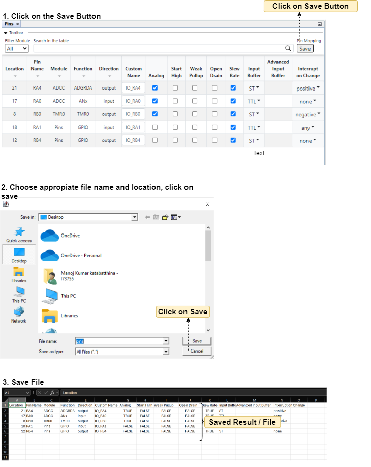
3.3.1.3 Save Pin Mapping
This feature allows users to save the pin mapping into csv format as per user needs.
3.3.2 Pin Grid View
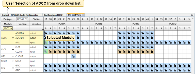
In the Pin Grid View, the device package can be selected from a drop-down list. The package selection is on the upper left side of the Pin Grid Table View. In the figure below, the drop-down list shows that the QFN64 package has been selected. The selected package will be displayed in the Package View. The pin numbers in the Table View will also show the pin numbers for the selected package.
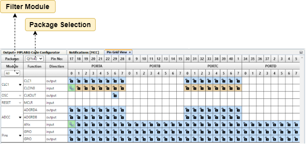
The three leftmost columns in the Table View indicate the module’s name, functionality name, and direction, respectively. The Table View allows to Expand and Collapse Rows.
3.3.2.1 Filter Module
This feature allows users to select a specific module from a dropdown list, which then displays all the pins that are locked within that module with a highlighted color.

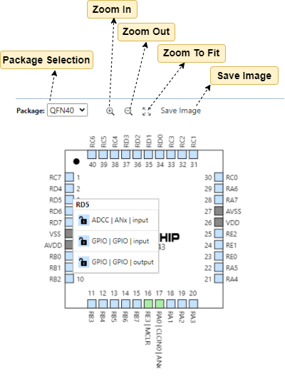
3.3.3 Pin Package View
The following color combinations are associated with the pins in Graphical or Table View:
| Color combinations | Description |
 | The pin is not usable in the selected configuration, and there is no enabled module that has any functionality on that pin. There are also grayed-out locks on a white background that indicate pins locked out by selected system functions. |
 | Pins that are available to be allocated to a module. |
 | The pin has been allocated and selected for a module. The name displayed against the pin is either the pin name of the module’s context or a custom name entered. |
The graphical Pin Manager can be zoomed in and out to adjust its visibility. This can be done by scrolling the mouse wheel when the mouse is over the Package View. Zoom In, Zoom Out and Zoom to fit can also be achieved by the buttons in the toolbar.
By right-clicking on a specific pin, all available pin functions are listed for selection. A snapshot of the package view configuration can be saved in PNG format by right-clicking on the package and selecting "Export Image."
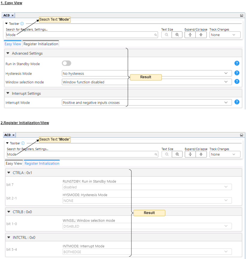
3.4 Component Views
Different views are presented when configuring an MCC Melody Components (such as Libraries, Drivers, PLIBs), different views are presented, depending on whether an easy or very detailed configuration is required.
For more information, see MCC Melody Components.
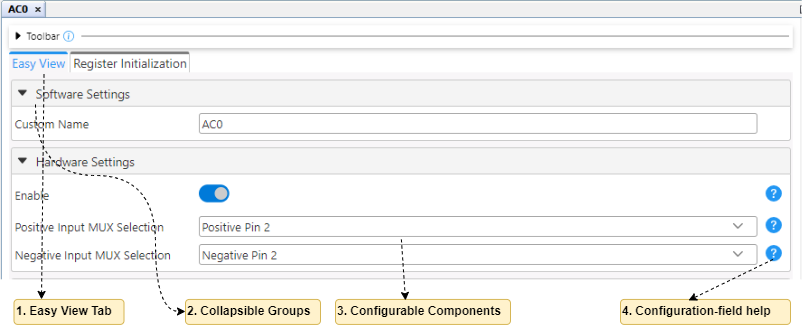
3.4.1 Easy View
Easy View allows users to interact with the Graphical User interface.
Users can interact with the Graphical User interface and use it to configure peripherals parameters of registers and settings.
| # | User Interface | Description |
|---|---|---|
| 1 | Easy View Tab | When a peripheral, library or other external component is selected from the Project Resources Area, its corresponding configuration GUI is displayed in Easy Views,where user configure the peripherals and libraries |
| 2 | Collapsible Groups | GUI controls (Register/Settings) are grouped according to their functionality, e.g., Software Settings, Hardware Settings, Interrupts |
| 3 | Configurable Controls | User configurable parameters are reflected into Register Values and Firmware Code |
| 4 | Configuration-field help | On-demand help for most UI components, which take users to the related |
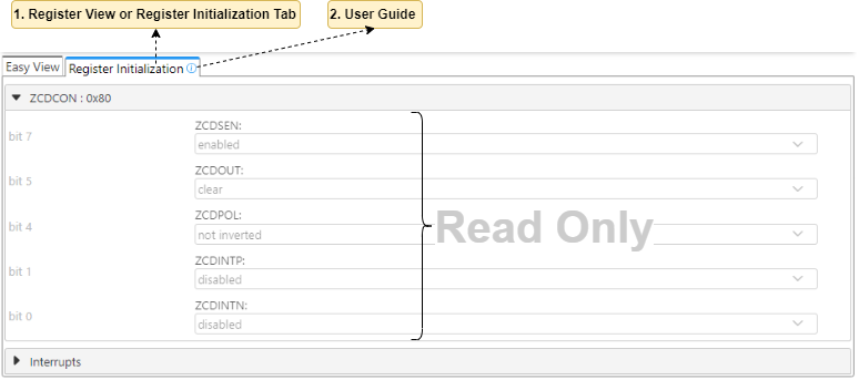
3.4.2 Register View/Initialization
Register View or Register Initialization is a read-only tab. It shows the resultant values of the registers based on Easy View changes and Firmware code is generated reflecting these values.
Any component configuration using the Easy View tab will be reflected in the values displayed in the Registers tab.
| # | User Interface | Description |
|---|---|---|
| 1 | Register View or Register Initialization Tab | Displays Register and Setting value |
| 2 | User Guide | Clicking this icon navigates to the Technical Reference User Guide, providing detailed information on the Register View |
| 3 | Read Only | Registers are non-editable |
3.5 Release Note Reference
Release notes are provided to document the updates, new features, improvements and bug fixes made to the MCC Melody Core.
The Melody Core release notes can be found at this Link.