
5.2.2.1 Application Logic
To develop and run the application, follow these steps:
- Open the
main.cfile of the project located in the source files folder. Add the following code outside the main() function:#define RX_BUFFER_SIZE 1 bool USART1_writeStatus = false; bool USART1_readStatus = false; bool USART0_writeStatus = false; bool USART0_readStatus = false; void USART1_WriteEventHandler ( uintptr_t context ) { USART1_writeStatus = true; } void USART0_WriteEventHandler ( uintptr_t context ) { USART0_writeStatus = true; } void USART1_ReadEventHandler (uintptr_t context) { USART1_readStatus = true; } void USART0_ReadEventHandler (uintptr_t context) { USART0_readStatus = true; } - In the following figure, the read and
write event handlers are declared same as the callback registers seen in the SAM D21
Curiosity Nano Evaluation Kit.
Figure 5-30. Event Handlers 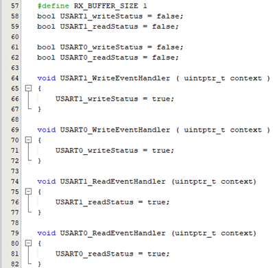
- Add the following code inside the
main()
function:
/* Initialize all modules */ SYS_Initialize ( NULL ); // EDBG SERCOM Read and Write Callback USART1_WriteCallbackRegister(USART1_WriteEventHandler, (uintptr_t)NULL); USART1_ReadCallbackRegister(USART1_ReadEventHandler, (uintptr_t)NULL); // Extension SERCOM Read and Write Callback USART0_WriteCallbackRegister(USART0_WriteEventHandler, (uintptr_t)NULL); USART0_ReadCallbackRegister(USART0_ReadEventHandler, (uintptr_t)NULL); uint8_t rxBuffer; - In the following code examples,
SYS_Initialize (NULL)initializes the modules like clock, Nested Vector Interrupt Controller (NVIC), Embedded Flash Controller (EFC), Parallel In/Out Controller (PIO), and USART. Also, the callback register functions for read and write operations are declared.Figure 5-31. Initialization of Modules 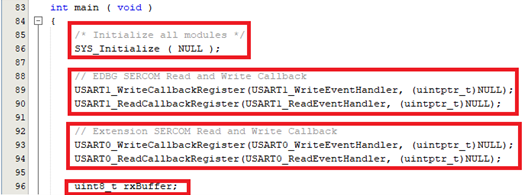
- Add the following code after the
initialization of
modules:
// Read request for EDBG USART1_Read(&rxBuffer, RX_BUFFER_SIZE); // Read request for Extension USART0_Read(&rxBuffer, RX_BUFFER_SIZE); - Start the implementation with a read
request for USART0 (for Extension) and USART1 (for EDBG).
Figure 5-32. Read Requests 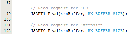
- Add the following code inside the
while loop:
if(USART0_readStatus == true) { USART0_readStatus = false; //Transmit received bytes from EDBG USART1_Write(&rxBuffer, RX_BUFFER_SIZE); } if(USART1_writeStatus == true) { USART1_writeStatus = false; USART0_Read(&rxBuffer, RX_BUFFER_SIZE); } if(USART1_readStatus == true) { USART1_readStatus = false; //Transmit received bytes from Extension USART0_Write(&rxBuffer, RX_BUFFER_SIZE); } if(USART0_writeStatus == true) { USART0_writeStatus = false; USART1_Read(&rxBuffer, RX_BUFFER_SIZE); } - In the following figure, if the
Extension is ready to read (Rx) the data (i.e.,
USART0_readStatus ==
                    true
), then it transmits the received data to EDBG, and if the Extension is ready to write (Tx) the data (i.e.,USART1_writeStatus == true), then EDBG will start a read (Rx) request. Similarly, vice versa if the EDBG is ready to read (Rx) or if the EDBG is ready to write (Tx).Figure 5-33. Implementation of Basic Configuration 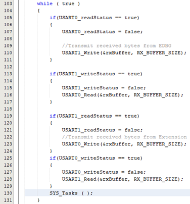
Figure 5-34. Host Side 
Figure 5-35. Client Side 