5.2.1.1 Application Logic
To develop and run the application, follow these steps:
- Open the
main.cfile of the project located in the ource files folder. Add the following code outside the main() function:#define RX_BUFFER_SIZE 1 volatile bool SERCOM_1_readStatus = false; volatile bool SERCOM_1_writeStatus = false; volatile bool SERCOM_5_readStatus = false; volatile bool SERCOM_5_writeStatus = false; void SERCOM_1_WriteCallback(uintptr_t context) { SERCOM_1_writeStatus = true; } void SERCOM_1_ReadCallback(uintptr_t context) { SERCOM_1_readStatus = true; } void SERCOM_5_WriteCallback(uintptr_t context) { SERCOM_5_writeStatus = true; } void SERCOM_5_ReadCallback(uintptr_t context) { SERCOM_5_readStatus = true; } - In the following code example, the
read callback and write callback are declared. These functions set the pointer to a
client function to be called when the given USART’s write or read event occurs.
These callbacks describe the pointer to the function to be called when the write or
read event has completed. By setting this to NULL, it can be disabled.
Figure 5-16. Event Handlers 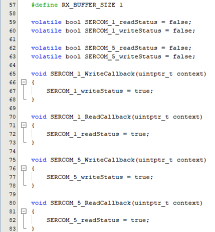
- In Figure 5-17,
SYS_Initialize (NULL)initializes the modules, such as ports, clock, SERCOM USART, Nested Vector Interrupt Controller (NVIC), and Non-Volatile Memory Controller (NVMCTRL). Also, the callback register functions for read and write operations are declared. - Inside the main() function, add the
following code:
/* Initialize all modules */
    SYS_Initialize ( NULL );

    // Extension SERCOM Read and Write Callback
    SERCOM1_USART_ReadCallbackRegister(SERCOM_1_ReadCallback, 0);
    SERCOM1_USART_WriteCallbackRegister(SERCOM_1_WriteCallback, 0);

    // EDBG SERCOM Read and Write Callback
    SERCOM5_USART_ReadCallbackRegister(SERCOM_5_ReadCallback, 0);
    SERCOM5_USART_WriteCallbackRegister(SERCOM_5_WriteCallback, 0);

    uint8_t rxBuffer;
Figure 5-17. Initialization of Modules 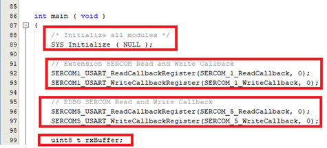
- Start the implementation with a read
request for SERCOM1 (for Extension) and SERCOM5 (for
EDBG).
// Read request for Extension
    SERCOM1_USART_Read(&rxBuffer, RX_BUFFER_SIZE);

// Read request for EDBG
    SERCOM5_USART_Read(&rxBuffer, RX_BUFFER_SIZE);
Figure 5-18. Read Requests 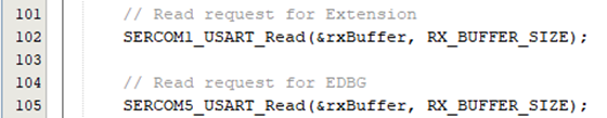
- In Figure 5-19, if the Extension is ready
to read (Rx) the data (i.e.,
SERCOM_1_readStatus == true), then it transmits the received data to EDBG. And, if the Extension is ready to write (Tx) the data (i.e.,SERCOM_1_writeStatus == true), then EDBG will start a read (Rx) request. Similarly, vice versa if the EDBG is ready to read (Rx) or if the EDBG is ready to write (Tx). Add the following code inside the while loop:if(SERCOM_1_readStatus == true) { SERCOM_1_readStatus = false; //Transmit received bytes from EDBG SERCOM5_USART_Write(&rxBuffer, RX_BUFFER_SIZE); } if(SERCOM_5_writeStatus == true) { SERCOM_5_writeStatus = false; SERCOM1_USART_Read(&rxBuffer, RX_BUFFER_SIZE); } if(SERCOM_5_readStatus == true) { SERCOM_5_readStatus = false; //Transmit received bytes from Extension SERCOM1_USART_Write(&rxBuffer, RX_BUFFER_SIZE); } if(SERCOM_1_writeStatus == true) { SERCOM_1_writeStatus = false; SERCOM5_USART_Read(&rxBuffer, RX_BUFFER_SIZE); }Figure 5-19. Implementing the Basic Configuration 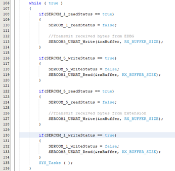
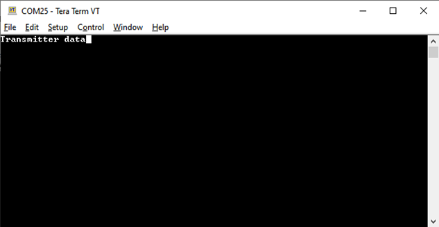
Figure 5-20. Host Side 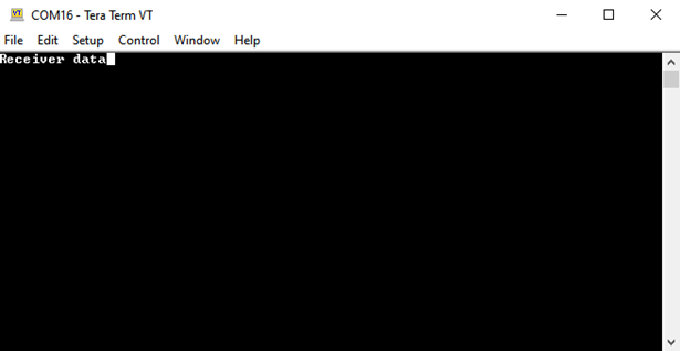
Figure 5-21. Client Side