
5.4.1.1 Application Logic
To develop and run the application, follow these steps:
- Open the
main.cfile of the project located in the source files folder. Add the following code outside the main() function:#define RX_BUFFER_SIZE 1 #define TX_BUFFER_SIZE 1 uint8_t rxBuffer; uint8_t txBuffer = 0xAA; volatile bool readStatus_SERCOM_1= false; volatile bool writeStatus_SERCOM_1 = false; volatile bool readStatus_SERCOM_5 = false; volatile bool writeStatus_SERCOM_5 = false; void APP_SERCOM_1_WriteCallback(uintptr_t context) { SERCOM1_USART_Write(&txBuffer, TX_BUFFER_SIZE); } void APP_SERCOM_1_ReadCallback(uintptr_t context) { readStatus_SERCOM_1 = true; } - In the following figure, the read
callback and write callback is declared. These functions set the pointer to a client
function to be called when the given USART’s write or read event occurs. Once the
read is completed, the write callback is called and the write function inside this
callback writes the data in the console. These callbacks describe the pointer to the
function to be called when the write or read event has completed. By setting this to
NULL, it will be disabled.
Figure 5-50. Event Handlers 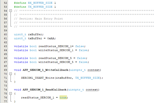
- Inside the main() function, add the
following code:
SYSTICK_TimerStart(); // Extension SERCOM Read and Write Callback SERCOM1_USART_WriteCallbackRegister(APP_SERCOM_1_WriteCallback, 0); SERCOM1_USART_ReadCallbackRegister(APP_SERCOM_1_ReadCallback, 0); // Read request for Extension SERCOM1_USART_Write(&txBuffer, TX_BUFFER_SIZE); SERCOM1_USART_Read(&rxBuffer, RX_BUFFER_SIZE); - In the following figure,
SYS_Initialize (NULL)initializes the modules, such as ports, clock, SERCOM USART, Nested Vector Interrupt Controller (NVIC), and Non-Volatile Memory Controller (NVMCTRL). The callback register functions for read and write operations are declared. Also, the SYSTICK times and the read and write request for SERCOM1 (for extension) is implemented.Figure 5-51. Initialization of Modules 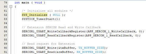
- Add the following code inside the while
loop:
SYSTICK_DelayMs(1U); if(readStatus_SERCOM_1 == true) { readStatus_SERCOM_1 = false; SERCOM1_USART_Read(&rxBuffer, RX_BUFFER_SIZE); } - In the following code example, to
visualize the hardware flow control using the RTS and CTS lines, a delay of one
millisecond is introduced in the code.
Figure 5-52. Implementation of Hardware Handshaking Configuration 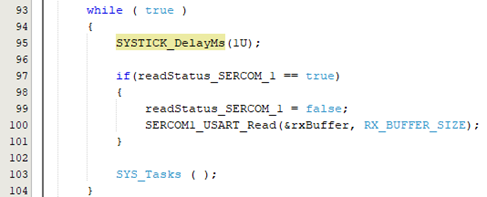
Figure 5-53. SAM D21 Curiosity Nano – Hardware Handshaking Output 