2.3.3 Plot Graph In MPLAB® Data Visualizer
MPLAB Data Visualizer is a program used to process and visualize data from a running embedded target. The program may be accessed as an MPLAB X IDE plugin or a stand-alone program. In this assignment, the Data Visualizer will be configured to graph ADC acquisitions received over USART. The configuration is done through a saved workspace, and the basics of how to display the data are explained. Click the Documentation button in MPLAB Data Visualizer for a detailed guide on how to set up your workspace.
Todo: Configure MPLAB Data Visualizer to graph received ADC samples.
- Open the program and plug in an
already flashed device. Make sure the COM-port used for USART communication is not
already in use. The start screen should be similar to Figure 2-5.
Figure 2-5. Assignment 1: MPLAB® Data Visualizer Starting Page - Load the workspace. Press the Load
Workspace button and add the workspace-file called Assignment1.json.
All the workspaces for this training can be found in
DataStreamerConfiguration. Two axes should appear in the graph. These can be configured on the panel on the right-hand side, as illustrated in Figure 2-6.Figure 2-6. Assignment 1: Data Visualizer Setup - Plot the data. Choose the COM-port on
the left-hand side panel seen in Figure 2-6.
Make sure the Baud Rate is 115200 and press Apply to set the baud
rate. Press the play button on the COM-port to start the USART communication. Press
the Variable Streamers button to connect the decider to the USART data
stream. Set the COM port as input to Decoder 1, as shown in Figure 3.
Figure 2-7. Assignment 1: Variable Streamers - Press Show Live Data to start plotting live data from the device. The axes
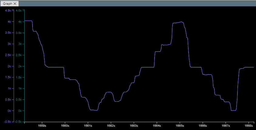
are on auto-range and will scale according to the input from the sensor. Figure 2-8 shows an example of the plotted result
when pushing the sensor with different pressure. Since the ADC is 12-bit, the
maximum range for the data will be within [0,4095].
Figure 2-8. Assignment 1: Single Mode Plot  Info: The decoder file decodes the data stream from the COM-port. The decoded sources are called Sample and Result. Sample is the value placed in the Sample register from a single conversion operation. Result is the value placed in the Result register. Depending on the operation, it can either be a single sample or a sum of multiple samples. In Single mode, there is a single conversion per trigger. Therefore, as seen in Figure 2-8, it is expected that the two sources are identical.
Result: The
MPLAB Data Visualizer has been configured to graph ADC samples received from
the nEDBG USART serial gateway.
