5 Running the Demo
(Ask a Question)This section describes steps to successfully run the demo and observe the Ethernet packets transmitted and received by the Ethernet test module. The following points describe the overview of the demo:
- The test module initiates the Ethernet traffic on the line. On the system side, the FPGA configures the AQR107 PHY. Then, Auto Negotiation (AN) packets are passed to CoreUSXGMII through AQR107 PHY and the auto negotiation is completed at the system side.
- The Ethernet traffic is received at USXGMII through XCVR lane which is connected to AQR107 PHY on 10G daughter board. Ethernet Packets are looped back at the USER FIFO located at CORE10GMAC system interface.
- The test module receives the packets from AQR107 PHY through Cat6 cable and checks for CRC errors. It displays the number of packets transmitted, received, errors received, and the line throughput.
Important: Before running the demo:
- Ensure that the demo hardware is setup as described in Setting Up the Demo.
- The user must know how to launch the test module software on the Host PC, discover the test module, and use the test module software.
To run the USXGMII demo, follow these steps:
- Configure the test module for 10GBASE-T advertisement using the test module software.
Figure 5-1. 10GBASE-T Advertisement 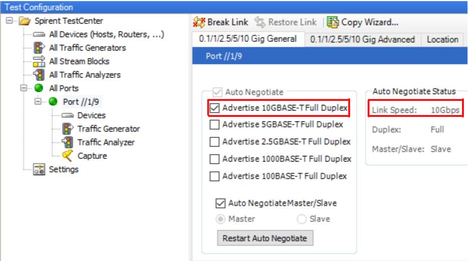
- Launch TeraTerm with the 3rd FlashPro5 Port and 115200 Baud rate.
Figure 5-2. TeraTerm Configuration 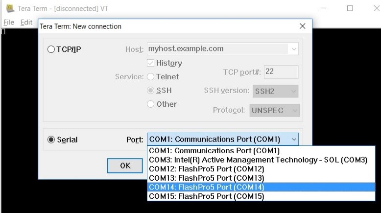
- Reset the design or power cycle the video board.
- Observe the UART messages for the completion of PHY initialization, AN enabled between the external PHY and USXGMII, MAC configuration, and the 10G clock configured message.
Figure 5-3. UART Message - 1 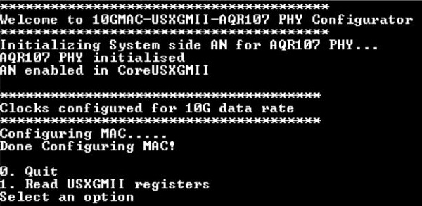
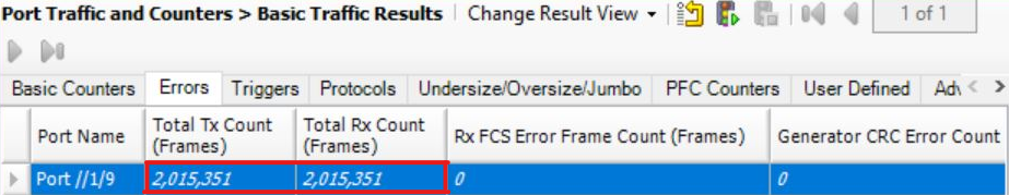
- Observe the 10G traffic transmitted and received by the test module.
Figure 5-4. 10G Traffic Report 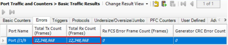
- Configure the test module for 5GBASE-T advertisement.
Figure 5-5. 5GBASE-T Advertisement 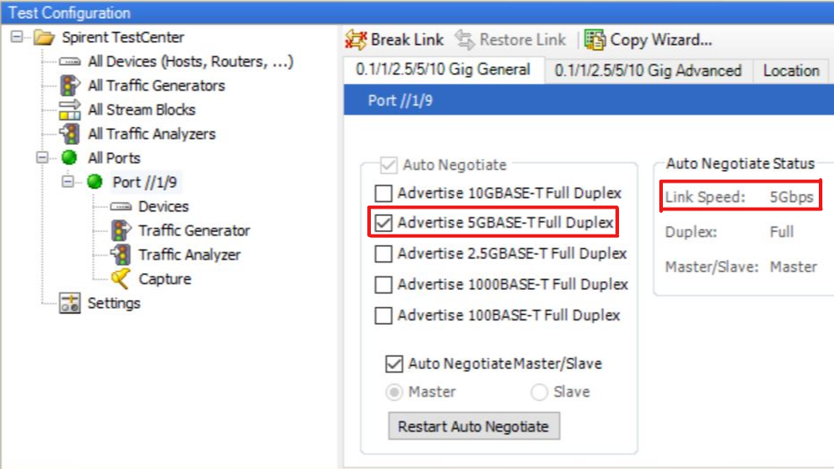
- Observe the clocks configured message for 5G data-rate on the TeraTerm.
Figure 5-6. UART Message -2 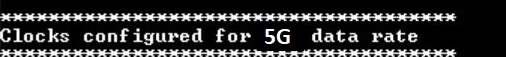
- Observe the 5G traffic transmitted and received by the test module.
Figure 5-7. 5G Traffic Report 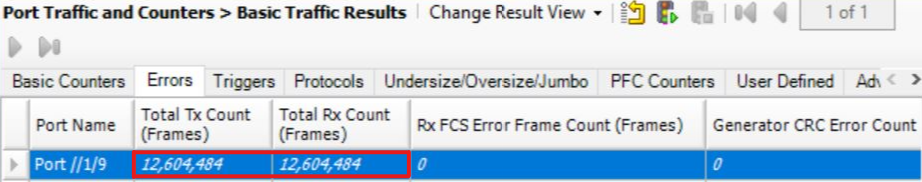
- Configure the test module for 2.5BASE-T advertisement.
Figure 5-8. 2.5GBASE-T Advertisement 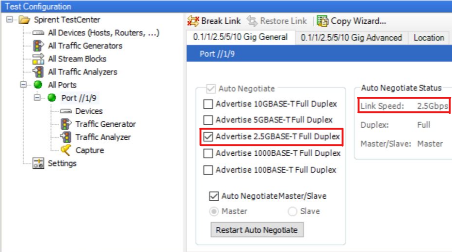
- Observe the clocks configured message for 2.5G data-rate on the TeraTerm.
Figure 5-9. UART Message - 3 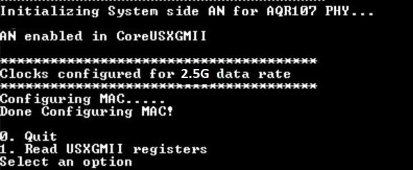
- Observe the 2.5G traffic transmitted and received by the test module.
Figure 5-10. 2.5G Traffic Report 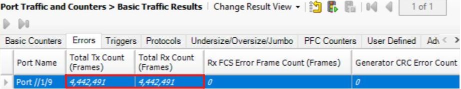
- Configure the test module for 1000BASE-T advertisement.
Figure 5-11. 1000BASE-T Advertisement 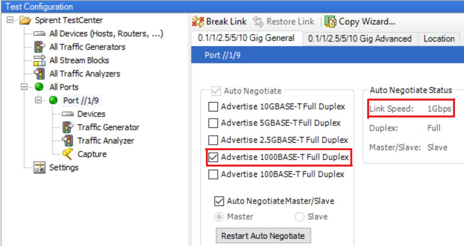
- Observe the clocks configured message for 1000BASE-T data-rate on the TeraTerm.
Figure 5-12. UART Message - 4 
- Observe the 1000BASE-T traffic transmitted and received by the test module.
Figure 5-13. 1000BASE-T Traffic Report