8 Simulation
How to simulate your configurable logic design.
8.1 Introduction
8.1.1 What Is Simulation?
The CLB Synthesizer Toolchain includes simple simulation functionality to check that your logic design functions as you intended.
To use the simulator, you must define a set of input patterns to run the simulation. The result of the simulation is a set of waveforms that you can inspect to check the behavior of your logic design when driven with the input patterns.
8.1.2 Quick Start
A convenient way to get started with simulation in the CLB Synthesizer toolchain is to look at an example.
Step 1: Navigate to the start page of the CLB Synthesizer.
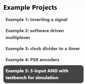
Step 2: Select Example 5 from the Example Projects section.
Step 3: Select the test bench document in the left-hand pane to open the test bench.
Step 4: Click the Simulate button on the bottom-left side of the window.
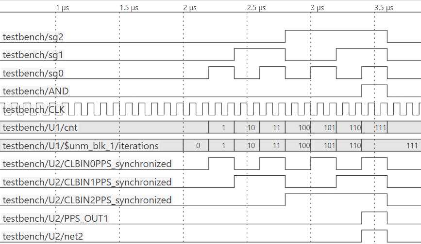
The simulation will run, and the waveforms will appear in a new tab window.
8.1.3 Concepts
Important concepts to understand when dealing with simulation.
Stimulus
A stimulus is a predefined pattern applied to your logic design to exercise and test its behavior.
Test Bench
In its simplest form, it is a test bench providing the stimuli that drive a simulation. It instantiates a Unit Under Test (your logic design) and connects its inputs to stimuli.
Some test benches also compare simulation outputs to expected outputs.
When making a test bench, you should attempt to create all possible input conditions to check every corner case of your design.
Unit Under Test (UUT)
A Unit Under Test (UUT), also known as a "Device Under Test (DUT)," refers to the item being tested. In logic simulation, this can be your entire logic design or specific components.
Simulation Viewer (VCD)
Simulation results are stored in the ASCII-based Value Change Dump (VCD) format. Data in VCD format is typically rendered in a graphical form for analysis in the GUI.
8.1.4 Warnings and Caveats
The CLB Synthesizer Toolchain provides a simple event-driven simulation environment that can verify your logic design behaves as expected. It only simulates your logic design and does not use any model of the actual CLB module to achieve this.
8.2 How to Run a Simulation
8.2.1 Creating a Logic Design for Simulation
Depending on how your design is architected or modularized, the simulation feature in the CLB Synthesizer toolchain can be used during or after the creation of your logic design and be performed on both the entire design (top-level/main) and submodules or sections of your logic design.
The CLB Synthesizer supports the creation of multiple test benches, which can test functional sub-sets of your logic design or exercise your logic design in various scenarios or conditions.
The first step in using the simulator is identifying the logic functionality you want to test. If this is not the top level (main) of your design hierarchy, it must be contained in a module (which may also include hierarchy modules).
When constructing your test bench, the module's interface (inputs and outputs) will become connection points for stimuli.
8.2.2 Making a Test Bench
Step 1: Create a New Test Bench Document
In the documents drawer menu in the CLB Synthesizer, select New Test Bench.
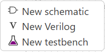
Give the test bench an appropriate name.
The new test bench will show in the documents section, and a new schematic canvas will appear in the editor.

Step 2: Place the Unit Under Test (UUT)
When a test bench document type is selected in the CLB Synthesizer, the modules section in the left side bar contains all available logic modules, including the top-level (main) module. The test bench can be considered hierarchically above the top-level logic design.
Select the module to use as the UUT in the new test bench and drag and drop it onto the test bench canvas.
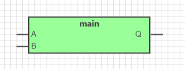
Check that the inputs and outputs on the module are correct.
Step 3: Place and Configure One or More Stimuli
When a test bench document type is selected in the CLB Synthesizer, a simulation stimuli section becomes available in the left sidebar. This section contains all available stimuli, which can generate inputs to your logic design during simulation.
Select an appropriate stimulus generator and drag and drop it onto the test bench canvas.
When a stimuli generator is selected, its properties can be configured in the right-hand properties panel.
For more information on stimuli types, see Stimuli.
Step 4: Connect the Stimuli to the UUT and Annotate the Test Bench
Each input to the UUT module must be connected to a stimulus source.

Adding net label elements to the connections can help enhance the test bench's readability and make the output more intuitive. Adding them to the UUT outputs is helpful, although not mandatory.
8.2.3 Running a Simulation
Step 1: Configure the simulation
Before running a simulation, configure the global test bench properties.
When clicking the canvas background inside a test bench, the test bench properties will appear in the right-side panel.
| Property | Description |
|---|---|
| Global Clock | "Global Clock" specifies the clock used for a simulation run expressed as either a period or a frequency, which is the clock source for all synchronous elements (flip-flops) in your logic design and/or test bench and should match the CLB clock in your actual design |
| Simulation Length | Specifies the duration of a simulation run in either number of cycles or timespan |
Step 2: Run the simulation
Click the "Simulate" button in the left-side panel to start a simulation run.

The logic design and test bench are sent to the simulation backend server for processing, and a new output will appear in the left-side panel.
8.2.4 Stimuli
How to provide inputs to a simulation run.
Multi-Bit Counter Stimuli
A counter stimulus (CNT) can exhaustively exercise a logic design by using a counter to iterate through all possible input combinations.
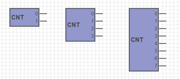
| Property | Description |
|---|---|
| Period | The counter period |
| Start Offset | The duration from the start of simulation before the counter is started |
| Repeats | Number of times to repeat the counter pattern upon wrapping |
| Repeat Delay | The delay duration after wrapping before the counter is restarted (if repeat is specified) |
| Counter bits | Number of bits in the counter, in the range between 3 and 32 |
Pulse-Width Modulation Stimuli
Use a Pulse-Width Modulation (PWM) stimulus to apply a repeating signal with a fixed duty cycle to a single input pin.
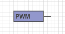
| Property | Description |
|---|---|
| Number of clock cycles | The number of clock cycles the PWM is to be active for |
| Period/Frequency | Specifies either the period or the frequency |
| Time spent high/Duty Cycle | Specifies the duty cycle either as a percentage or time in the high-state |
UART Stimuli
Use a UART stimulus to apply a UART bit stream corresponding to an ASCII string to a single input pin.
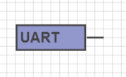
| Property | Description |
|---|---|
| Baud rate | The UART waveform baud rate in bps. The resulting period of a single bit is displayed. |
| Message | The ASCII string to be sent by the UART stimulus |
| Sent message n times | The number of times the same message is to be sent |
| Stop bits | Select either one or two stop bits for the UART |
| Parity | Select odd, even or no parity |
| Delay between Messages | Specifies the delay between repeated messages (strings) in UART clock cycles |
| Delay between Frames | Specifies the delay between characters in UART clock cycles |
SPI Stimuli
Use a Serial Peripheral Interface (SPI) stimulus to apply an SPI bit stream corresponding to an ASCII string to a set of SPI input pins.
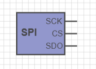
| Property | Description |
|---|---|
| Period/Frequency | Specifies either the period or the frequency of the SPI clock (SCK) |
| Message | The ASCII string to be sent by the SPI stimulus |
| Send message n times | The number of times the same message is to be sent |
| Bit order | Specifies to send either the Least Significant bit (LSb) or Most Significant bit (MSb) first |
| Delay between messages | Specifies the delay between repeated messages (strings) in SPI clock cycles |
| Delay between Frames | Specifies the delay between characters in SPI clock cycles |
Bit Pattern Stimuli
Use a bit pattern stimulus (BIN) to apply a fixed sequence of bits to a single input pin. The bit sequence can also be specified as a hexadecimal number (nibble-sequence), which is applied to four pins.

| Property | Description |
|---|---|
| Period/Frequency | Specifies either the period or the frequency of the bit pattern |
| Binary pattern | Pattern to send as either binary or hexadecimal |
| Send pattern n times | The number of times the same pattern is to be sent |
| Start offset | The duration from the start of simulation before the pattern is sent |
| Delay repeat | The delay duration after wrapping before the pattern is restarted (if repeat is specified) |
| Idle state | Specifies either high or low Idle state between patterns |
8.3 Viewing Simulation Results
8.3.1 Outputs
The result of a simulation run is a Value Change Dump (VCD) file.
After a successful simulation, a new file will be added to the output section in the left-hand panel with ‘-vcd’ appended to the test bench document name. After each simulation run, the file will be overwritten with a new instance. Rename the file by clicking the ‘Edit name’ icon and entering a new name to circumvent overwriting a simulation result.

- Save simulator result—Use this option to store the entire CLB archive, including inputs and debug information
- Save VCD file—Use this option to store only the VCD file

8.3.2 Navigating the VCD Output View
Panning and Zooming
Inspecting the simulation output is best done using a mouse with a scroll wheel.
To pan to the timestamp you want to inspect, click the primary mouse button and drag the waveform in the corresponding direction. Using the mouse scroll wheel while holding the <Shift> key will also pan the display.
You can also pan on the vertical axis if many signals are displayed
To zoom in or out, use the mouse scroll wheel.
Signal Selection and Filtering
The signals section in the left-hand panel contains a tree view of all signals available in the VCD output view, with the test bench name at the top of the hierarchy. The Filter section determines which signal types are available and can be selected.
- CLK—the global clock
- Net names annotated onto the schematic
- U1, U2...Un hierarchical sub-modules and stimuli generators with their respective inputs and outputs
- Internal/test bench-related signals in bold with $ prefixed
8.3.3 Markers and Measurements
Markers
Markers are a convenient way to annotate your VCD output waveform to ease navigation.
The Markers and Ranges section in the right-hand pane is active when viewing a VCD output file. Select +Add marker and click with the mouse at the appropriate location in the waveform to add a new marker. The mouse cursor snaps to the nearest flank of the signal it hovers over, even though a marker is located at a point in time and spans all signals.
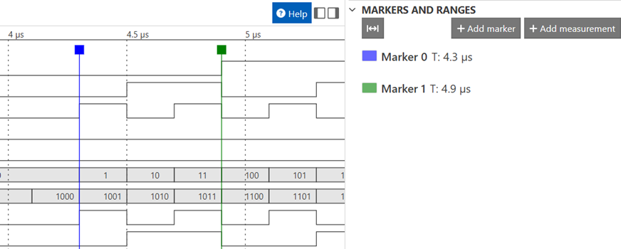
Currently listed active markers in the Markers and Ranges view, together with the location on the time axis. Use the Go to marker action button to return to a marker and the Delete action to remove a marker.
Measurements
Measurements are a mechanism to measure the interval between two points on the time axis.
The Markers and Ranges section in the right-hand pane is active when viewing a VCD output file. To make a new measurement, select +Add measurement, click with the mouse at the appropriate starting timestamp, drag the range left or right, and release the mouse button at the end of the measurement range. The mouse cursor snaps to the nearest flank of the measured signal.
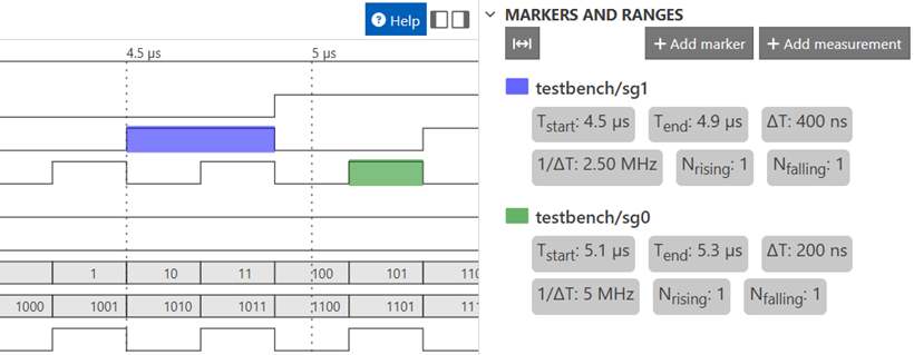
| Field | Description |
|---|---|
| Tstart | The start timestamp of the measurement |
| Tend | The end timestamp of the measurement |
| ∆T | The time interval between start timestamp and end timestamp |
| 1/∆T | The frequency corresponding to the interval measured |
| Nrising | The number of rising edges within the measurement range |
| Nfalling | The number of falling edges within the measurement range |
8.4 Further Information About Simulation
The Microchip CLB Synthesizer Toolchain simulation functionality is provided as an online service. The service makes use of the open-source Icarus Verilog simulator toolchain.
Advanced users can install their own local Icarus simulator to run local simulations.
To view the Verilog sent to the simulation server, enable the Show HDL setting in the CLB Synthesizer preferences accessed in the main drawer menu. The generated HDL section in the right-hand panel shows the active source for the schematic or test bench.
