4 Tips and Tricks
Productivity tips and tricks for the CLB Synthesizer.
4.1 How to Make Use of Limited Display Resources
Tips for using small displays.
When using the CLB Synthesizer inside MCC the amount of display real-estate available for logic drawings becomes constrained. It is possible to float the logic editor view to mitigate this.
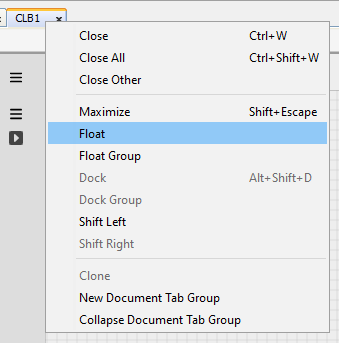
Right click the CLB1 tab and select Float from the menu.

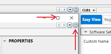
The CLB1 tab can then be moved onto an additional display or maximized on the current display by clicking one of the maximize buttons at the top of the window.

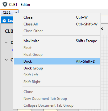
To restore the layout right-click the CLB1 tab and select Dock from the menu.

It is also possible to toggle the side and lower panels on and off using the control on the upper right side of the editor window:

- The left control toggles on and off the component palette to the left of the editor window
- The middle control toggles on and off the problems panel at the bottom of the editor window
- The right control toggles on and off the properties panel to the right of the editor window
4.2 Tidying up a Design
Making a logic design orderly and readable.
Selecting a signal will show what nodes are available for altering the path it takes. Elbow nodes are shown as squares and are used to move the node itself, while and mid-point nodes are diamond-shaped, and are used to split a line into additional segments.

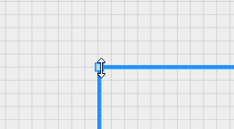
Hovering over an elbow node indicates which axes are available for altering the location of that node. Dragging this node in one of the indicated directions will move the location of that node.

-
Hovering over a mid-point always shows that is can be moved (split) in any direction

-
Dragging a mid-point node splits the section into two segments and moves the location of the split-point accordingly

- Split segments can be joined by manually aligning the two segments by dragging the elbow node; dragging the mid-point will create an additional split
- Modules: By extracting functional parts of a design into separate documents, a logic design can be divided into several hierarchical layers. This not only makes the top-level (main) schematic more tidy and readable, but allows the modules to be used multiple times in the same design without duplication. For more information, see Using Hierarchical Modules.
- Net labels: If the same signal needs to be used on opposite sides of a schematic a net label can be used instead of drawing a wire across the schematic. For more information, see Net Labels.
-
Input ports can be duplicated in cases where the same input signal is required in multiple places. This may help to reduce congestion of signals, but may reduce maintainability.
Note: It is possible to use the same input more than once with a different input synchronizer setting on each instance. - Rotate and flip: All components can be rotated and flipped so that they can be aligned to suit the signals they are connected to. Right-click a component or port on the canvas and select the function from the context menu, or select the item and use shortcut keys <R> (rotate), <X> (horizontal flip) or <Y> (vertical flip).
- Comments: Adding comments to a schematic improves readability and can be used to add context to the design itself.
