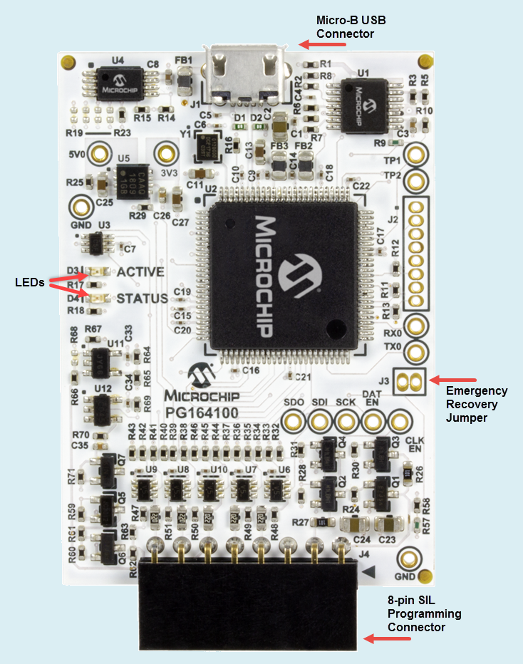
The debugger consists of an internal main board and an external Micro-B USB connector and
an 8-pin SIL connector. On the front of the debugger board has two LEDs and a jumper.
Figure 10-1. MPLAB® SNAP IN-CIRCUIT DEBUGGER
Micro-B USB Connector - Used to
connect the debugger to the computer with a high quality USB High Speed
cable (user supplied).
LEDs - Displays the operational
modes of the debugger.
Pin 1 Marker - This designates
the pin 1 location for proper connector alignment.
Programming Connector - The
connector is an 8-pin SIL header (0.100" spacing) that connects to the target
device (see Pinouts for Interfaces).
Emergency Recovery Jumper - For
use with the emergency boot firmware recovery utility only.
The online versions of the documents are provided as a courtesy. Verify all content and data in the device’s PDF documentation found on the device product page.