
1 MCC Melody 8-Bit MDFU Client Library
Introduction
The 8-Bit Microchip Device Firmware Update (MDFU) Client library in MPLAB® Code Configurator (MCC) Melody is the new implementation of the 8-Bit Bootloader library. Refer to the library Release Notes for the list of supported devices, along with version information, dependencies and required versions for MCC libraries and drivers.
Bootloader Overview
A bootloader is used when the user or manufacturer wants to update the firmware of their device in the field with a new application while minimizing device downtime. To do this, the device in the field needs some type of communication method capable of passing data between the device that needs an update (the “target device”) and a PC or other device which holds the new application firmware that needs to be installed (the “host application”). This implies that the device in the field must contain not only the end application, but also another piece of software that controls the loading and unloading of that end application. While its possible for each application to write their own handler to achieve this, writing firmware to update another firmware on a device is a nontrivial process that usually requires a deep understanding of the device operation, the software compiler and linker options, as well as the software running on the updating device, such as a PC. Because of this steep and broad learning curve, Microchip provides the MDFU ecosystem for their devices in an easy-to-configure library.
MDFU Ecosystem
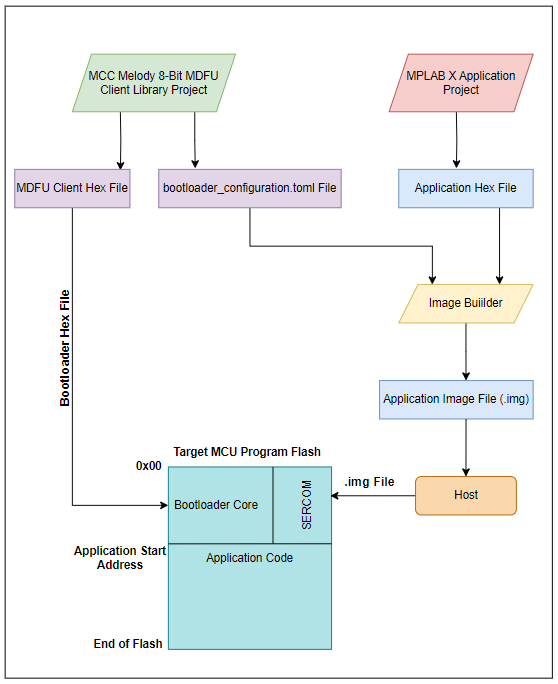
An MDFU ecosystem has four main parts: the Bootloader Client Firmware, End Application, Image Builder (pyfwimagebuilder) and Host Application (pymdfu).
The bootloader firmware is always the entry point when the device comes out of a Reset state. Its first task is to verify whether or not the application on the device is valid. If the application is verified, program counter is loaded with the application start address to start execution of the userʹs application. If verification fails, step into the bootloader operation cycle and wait for an attempted bootloader task to be started by the host application. The bootloader can also check for specific signals on the device to start the update process of the firmware. This could be as simple as checking the value of a General Purpose Input/Output (GPIO) pin or checking for a specific type of traffic on the Universal Asynchronous Receiver and Transmitter (UART), indicating that there is a new application firmware version that needs to be installed.
The end application is the second part of the infrastructure. This is a suite of code fully written and controlled either by the user or the manufacturer, and it is this application that will be installed by the bootloader. Future sections of this document show an example bootloader project where a blinking LED application is used to demonstrate how to start loading a custom application with a bootloader solution.
The image builder pyfwimagebuilder is a Python command line utility developed to
convert the application hex file into another format that is understood by the target
bootloader client firmware. The pyfwimagebuilder tool expects two input arguments and one
output argument to generate the image file to be loaded into the host application. First input
argument is the application hex file. Second input argument is the bootloader configuration
file (bootloader_configuration.toml). Third command line argument is the
image file name that upon generation will contain the application program code along with
other device configurations necessary for the firmware upgrade. The generated file, along with
the actual application program data, contains the device parameters such as Memory Unlock
keys, Flash memory row size, application start address, Device ID, etc. The content of this
file, upon loading in the host application is parsed and packetized to be sent to bootloader
client firmware running in the target device. The pyfwimagebuilder application can either be
invoked manually or as a post-build process in MPLAB X IDE to convert the generated
application hex file to the image file loaded into the host application.
Verification Features
A bootloader is the low-level code that runs when the device comes out of a Reset state. Its main purpose is to check if there is a new application image that needs to be installed on the device and, if there is, provide a path to accomplish this task. More features can be added into bootloaders that improve their performance and safety. One example of an important feature of any bootloader is the bootloader’s verification options. Bootloaders provide these verification schemes to check the validity of the application code before transferring control to the end application. Microcontrollers (MCUs) are basically just small computers and therefore should be protected just like any other computer system. To do this with a bootloading process, the bootloader needs to be able to identify errors in the application code before running it, which inherently protects the MCU from running malicious or corrupted code. Read more on this topic in the Verification Schemes chapter.
Memory Provisioning Features
Another feature of the MCC Melody 8-Bit MDFU Client is its communication interface, specifically designed to warrant the communication of commands used for transferring bytes of the application image into the MCU program memory. To utilize a bootload process, the bootloader code must be programmed into the Flash memory of the microcontroller unit. It is necessary to provision the MCU’s Flash memory to prevent writing in the boot section, as well as to tell the MCU where to write the new application image and how much data the application is allowed to access. Bootloader Memory Map shows the provisioned memory layout of a general bootloader solution.
