2 Setup the SPI
The configuration of the SPI in master mode will be shown in two different ways. The first example will show how to implement an SPI communication which is controlled by polling the interrupt flags. The second example will show how to implement an interrupt controlled communication.
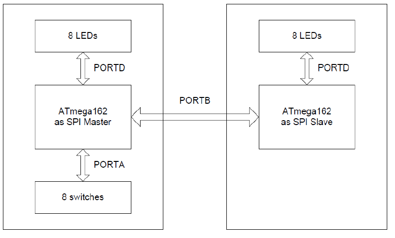
A communication between two AVR devices is shown by sending a text string from the part configured as master to the other part configured as slave. The received character is compared with the expected one (transmitted character) and the result of this communication test is output on the Port D in slave. These examples are well suited to be implement by using two development boards like the STK®600.
In all the examples shown here the SPI is configured to run in mode 0 with MSB transmitted first. This is done by setting the bits CPOL, CPHA and DORD in the register SPCR to zero. In the same register the SPI is enabled by setting the SPE bit, while the SCK frequency is specified to CK/4 in the first example . It is set to CK/16 in the second example.
- Because both examples show the transmission between a single master and a single slave it is not necessary to check if the MSTR bit is still set before the master initiates a new transmission. This code has to be added in a multi master application.
- Although the settings of the Clock Rate Select bits have no effect in slave mode it has to be ensured that the system clock (CK) of the slave is at least four times higher than the SPI clock (SCK).
- Pending SPI interrupts are cleared by a dummy access to the SPSR and the SPDR.
Both the master and the slave projects developed in Atmel Studio 7 are available along with this application note.