6.3 Timer Example (PLIB) - PIC16F/18F
6.3.1 Running the Timer Toggle LED Example
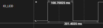
The image shows running the Timer Toggle LED, verifying the 100 ms period using Debug GPIO on the MPLAB Data Visualizer. An example Curiosity Nano is used, but the example can be configured to run on any board.
-
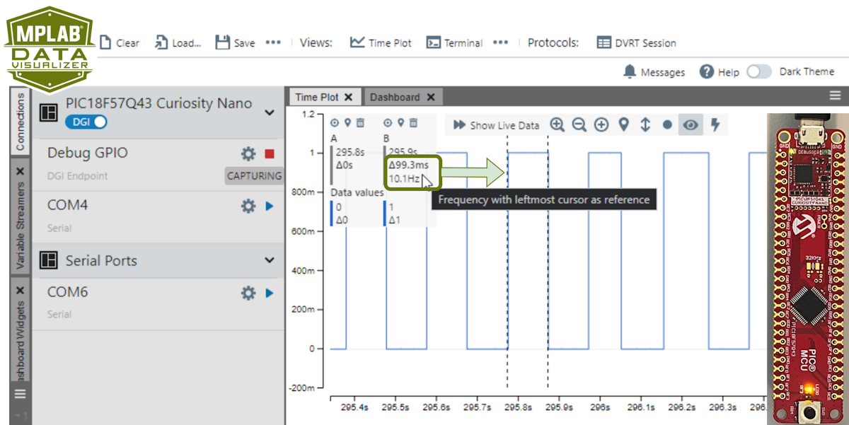 Tip: Two vertical cursors are added to verify the timer frequency. See configuration instructions below.Tip: A logic analyzer can be used instead of Debug GPIO on the MPLAB Data Visualizer.
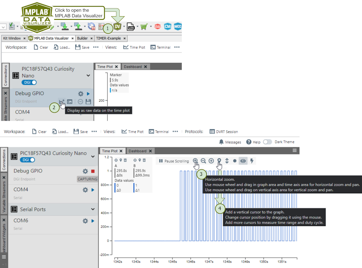
6.3.2 Running the Timer Switch Frequency Example
What will you see when running the Timer Switch Frequency example?
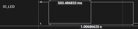
An initial run of the Timer Switch Frequency example shows the LED on the board flash at a 500 ms period interval. Pressing the assigned button will swap the period between 500 ms and 100 ms.
-
Example 500 ms:
-
Example 100 ms:
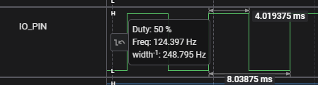
6.3.3 Running the Timer 125 Hz Output Signal Example
What will you see when running the Timer 125 Hz Output Signal example?
When running the Timer 125 Hz Output Signal Example, an 125 Hz output can be measured on the selected pin.
-
Output: