1.3 Port Access for LED
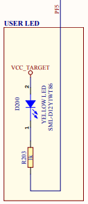
Each I/O pin Pxn can be controlled by the registers in PORTx. Each pin group x has its own set of PORT registers. For this example, PF5 of PORTF is used to turn the User LED on or off. Examining the board schematics shows that PF5 must be low for the LED to be lit and high for the LED to be off. Find the schematics link in the Kit Window.

Digital I/O device pins may be multiplexed with peripheral I/O pins. To ensure that you are using digital I/O only, disable the other peripheral(s). Do this by using the predefined C variables that represent the peripheral registers and bits. These variables are listed in the device-specific header file in the compiler include directory. To determine which peripherals share which pins, refer to your device data sheet.
To use PF5 as an output only pin, write bit 5 in the PORTF.DIRSET register to '1'. To do this without disturbing the value of the other bits, masks are provided for each register bit. In this case, PIN5_bm = 00001000.
PORTF.DIRSET = PIN5_bm; // set PF5 to be output
Writing bit 5 in PORTF.OUTCLR to '1' will clear that bit (set to ‘0’). This will turn the LED on.
PORTF.OUTCLR = PIN5_bm; // clear PF5 - LED on
Alternately, writing bit 5 in PORTF.OUTSET to '1' will set that bit (set to ‘1’). To turn the LED off, comment out the above instruction and uncomment the following instruction.
PORTF.OUTSET = PIN5_bm; // set PF5 - LED off
To view information on PORT registers, highlight a register name in the Editor, right click, and select Navigage>Online Datasheet.
