1.1 Configuration Bits
Microchip devices have configuration bits, or fuses, that enable and/or set up device features.
Which Configuration Bits to Set
In particular, be aware of the followings settings:
- Oscillator configuration - This must
match your hardware’s oscillator circuitry. If this is not correct, the device clock
may not run. Typically, development boards use high-speed crystal oscillators. From
the example code:
FUSES = { ... .OSCCFG = 0x02, // OSCCFG {FREQSEL=20MHZ, OSCLOCK=CLEAR} ... } - Watchdog timer configuration- It is
recommended that you disable this timer until it is required. This prevents
unexpected Resets. From the example code:
FUSES = { .WDTCFG = 0x00, // WDTCFG {PERIOD=OFF, WINDOW=OFF} ... } - Code protection - Turn off code
protection until it is required. This ensures that device memory is fully
accessible. From the example code:
LOCKBITS = 0xC5; //
                        {LB=NOLOCK}
#pragma config. For details,
see the “MPLAB® XC8 C Compiler User’s Guide for AVR® MCU” (DS50002750).See your device data sheet for the name and function of corresponding configuration bits. Use the part number to search www.microchip.com for the appropriate data sheet.
For more information about configuration bits that are available for each device, see the following file in the location where MPLAB XC8 was installed:
MPLAB XC8 Installation Directory/docs/avr_chipinfo.html
How to Set Configuration Bits
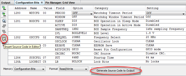
In MPLAB X IDE, you can use the Configuration Bits window to view and set these bits. Select Window>Target Memory Views>Configuration Bits to open this window.
For AVR devices, click  to read configuration memory, i.e., FUSES and LOCKBITS
values.

Once the settings are selected, click in code where you want this information placed and then click the Insert Source Code in Editor icon, as shown in the example code. Alternatively click the Generate Source Code to Output button to copy and paste into code.
See MPLAB X IDE documentation for more information on this window.
