
3.4 Hardware Setup
- The Curiosity High Pin Count (HPC) Development Board (DM164136) is used as the test platform. Switch S2 is used to test button debouncing. An external rotary encoder from the XMEGA-E5 Xplained board is used to test encoder debouncing. Onboard LEDs D2, D3, D4, and D5 are used to detect light respectively when debouncing on S2 and external encoder occurs.
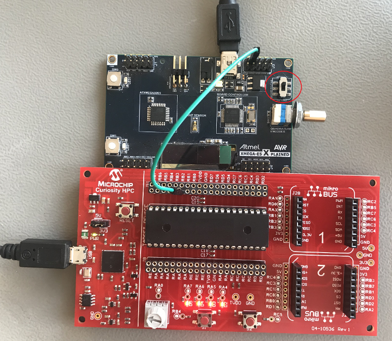
- The XMEGA-E5 Xplained board uses the USB power supply. The encoder pin, J3→GPIO3 on the XMEGA-E5 Xplained board, is connected to the debouncing input pin RB2 of the HPC board. Also, make sure the switch is set to route the encoder to J3 in the Header J3 as highlighted in the red circle in Figure 3-1.
- The HPC uses the USB power supply, configured to 3.3V VCC by a jumper
The table below shows the external encoder pin connection from the HPC board to the XMEGA-E5 Xplained board.
| HPC | XMEGA-E5 Xplained board |
| RB2 pin | GPIO3 pin |