
4.1 Adding Chip Peripherals
This document will provide some information about adding peripherals. The process of adding peripherals is explained with an example of "UART with Peripheral Pin Select".
The Peripheral Pin Select (PPS) feature allows digital signals to be moved from their default pin location to another location. To enable a digital peripheral’s input and/or output signals, the appropriate PPS registers must be configured.This can be extremely handy for routing circuit boards. There are cases where a change of I/O position can make a circuit board easier to route. Sometimes mistakes are found too late to fix so having the option to change a pinout mapping in software rather than creating a new printed circuit board can be very helpful.
Create a new MCC project.
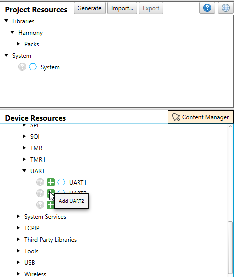
In "Device Resources" window, from "Peripherals", add "UART2" to the porject graph.
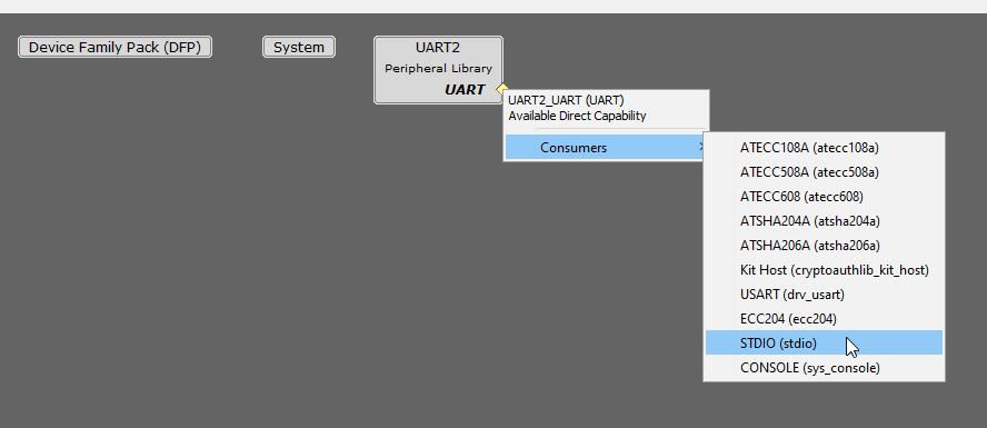
In the project graph, select the consumer as "STDIO" for UART2 as shown below.
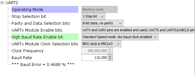
The required configuration of UART2 is shown below.
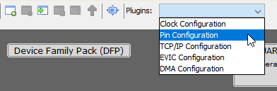
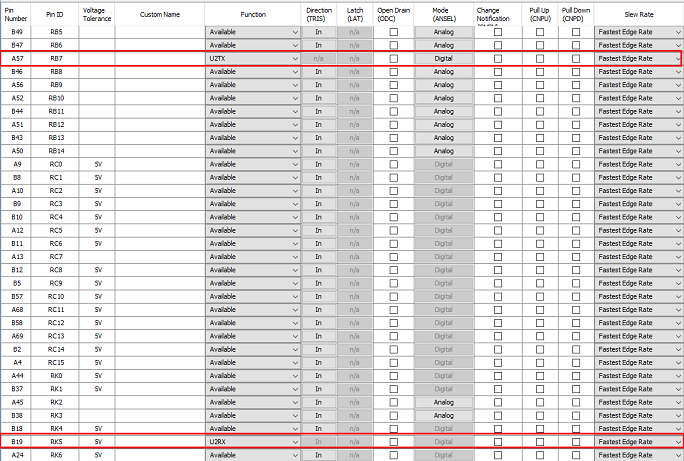
Open "Pin configuration" from "Plugins" as shown below.
For pin ID "RB7", select the "Function" as "U2TX" and for pin ID " RK5", select the "Function" as "U2RX". These pins are avialble in the "XPRO HEADER" of Curiosity board (Pin15 - RB7, Pin17 - RK5)
In "Project Resources" window, press "Generate" to generate the code.
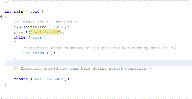
In "main.c" use "printf" to create a "Hello World" application example like this:
Build and program the application.
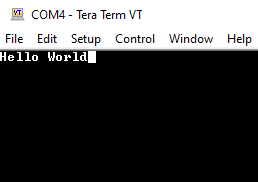
Make the proper connection at the "XPRO HEADER" of curiosity board. Open TeraTerm (Speed: 115200, Data: 8-bit, Parity: none, stop bits: 1 bit, Flow control: none) and select the COM port that is enumerated when connecting the Curiosity Board. Reset the board and your application example will output the message in Teraterm.
User can add any peripheral as explained above and do the proper peripheral and pin configuration.