3.1 Inductor and Input/Output Capacitor
The first choice of components is the inductor, L, which is used in conjunction with the output capacitor, Cout, for filtering the output voltage, stabilizing it around the targeted output voltage. The main consideration for this component is to limit the current ripple in the regulator, and its value is, therefore, based on the specified inductor current ripple, ΔI:
Where is the duty cycle of the switch. In situations where a range of input voltages is required, the inductor is dimensioned for the highest rated voltage, as this is when the ripple current is largest.
Cout is chosen next to complete the output filter. The charge in the capacitor will counteract the output voltage ripple and, therefore, its value is decided according to the maximum output voltage ripple, ΔVout. Its minimum value can be calculated using the following equation:
Add an input capacitor to stabilize the voltage further. This value can be calculated in the same way as the output capacitor, but for most applications, a 10 µF ceramic capacitor will suffice.
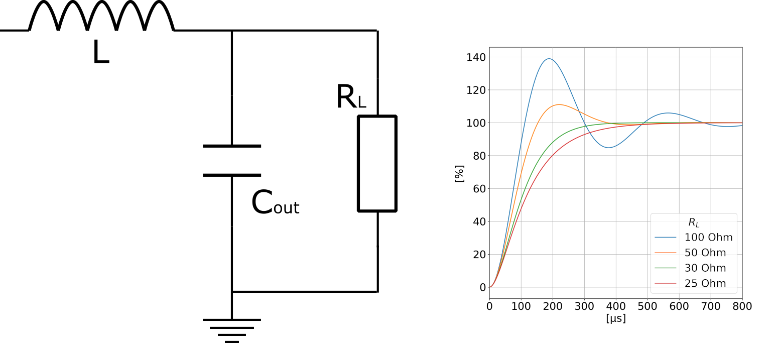
The duty cycle used in the calculations above does not take into consideration the changes in the load resistance, RL, which affect the step response of the output filter, as seen in Figure 3-2. A margin of 10-20% may be added to the maximum duty cycle to make sure the components are within specs for the full operating range.